A bend pipe forging die with spring material device

A technology of elastic material and pipe bending, which is applied in forging/pressing/hammer devices, manufacturing tools, forging/pressing/hammering machinery, etc., which can solve the problem that the finished pipe cannot be removed from the mold in time, and achieve simple structure , reduce labor intensity and facilitate operation

Active Publication Date: 2019-01-01
JIANGSU MINGGE FORGING EQUIP CO LTD
View PDF6 Cites 1 Cited by
  • Summary
  • Abstract
  • Description
  • Claims
  • Application Information

AI Technical Summary

Problems solved by technology

[0005] The object of the present invention is to: aim at the problem that the finished pipe cannot be removed from the mold in time after the processing of the existing pipe bend forging die, the present invention provides a pipe bend forging die with an elastic material device

Method used


Image

  • A bend pipe forging die with spring material device
  • A bend pipe forging die with spring material device
  • A bend pipe forging die with spring material device

Examples


Embodiment 1

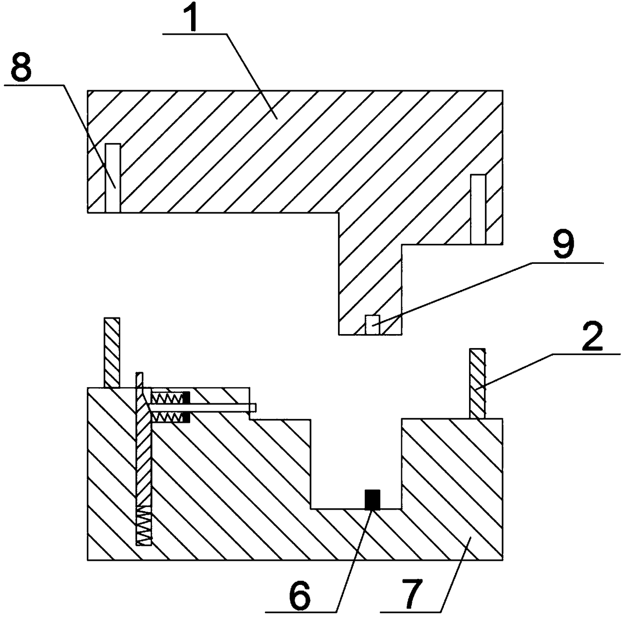
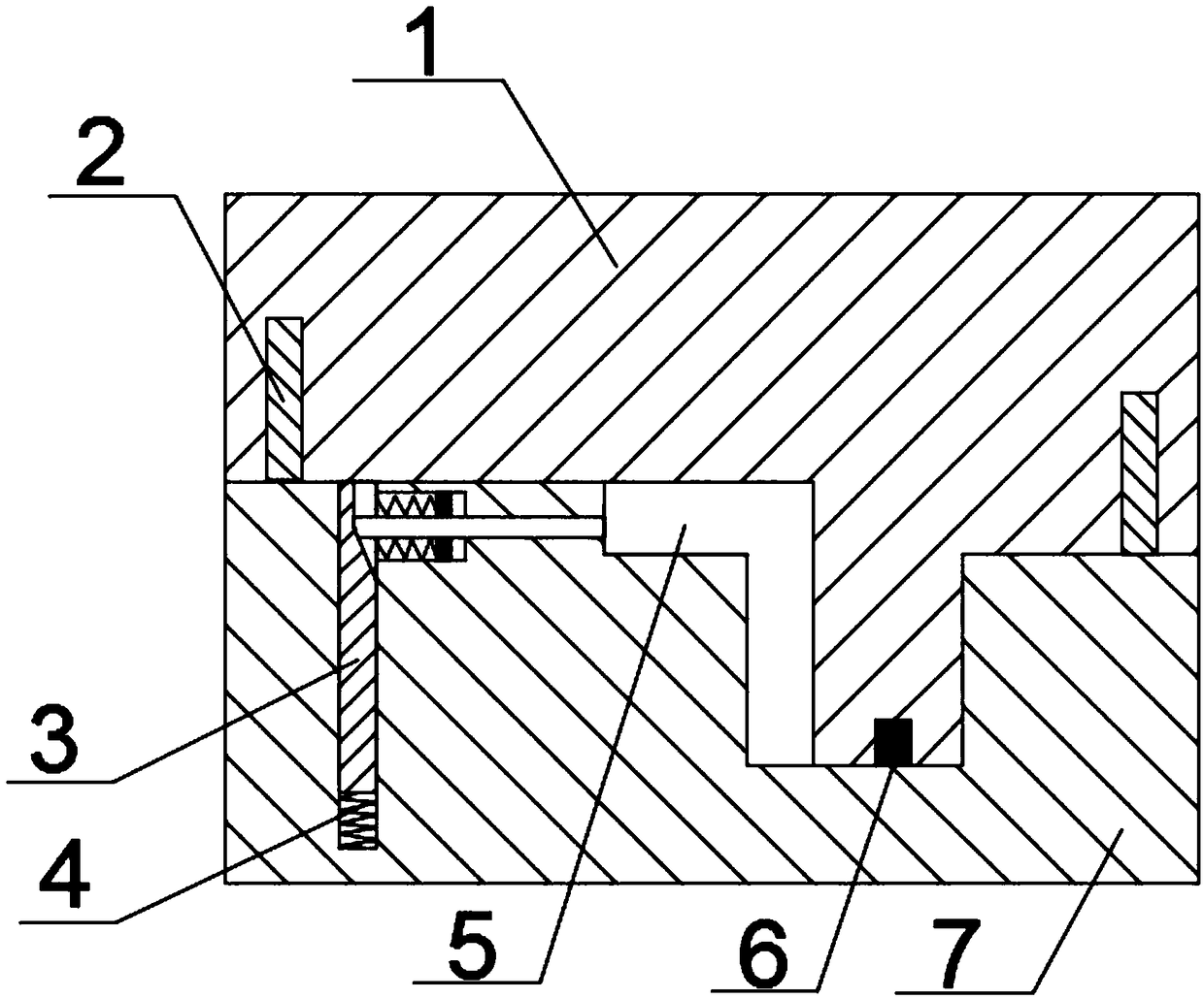
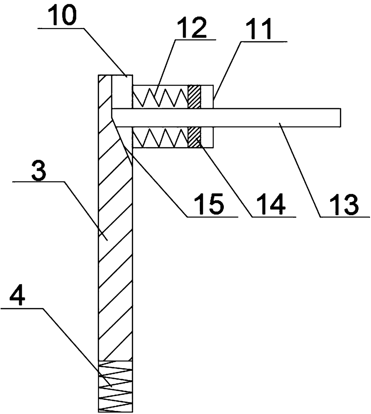
[0024] A bent pipe forging die with an elastic material device, comprising a fixed die 1 and a movable die 7 arranged below the fixed die 1, a convex die is arranged on the forging surface of the fixed die 1, and a forging die is arranged on the forging face of the movable die 7. The concave mold matched with the punch, the punch and the concave mold cooperate to form a forging cavity 5 matching the shape of the elbow; the movable mold 7 is equipped with an elastic material device, and the forging surface of the movable mold 7 has a downward blind hole 10. The spring material device includes a first spring 4 arranged at the bottom of the blind hole 10 and a pressing rod 3 arranged on the first spring 4. The upper end of the pressing rod 3 extends out of the blind hole 10. The upper part of the pressing rod 3 is a wedge-shaped surface 15, wedge-shaped A through hole 11 is opened at the position corresponding to the forging cavity 5, and a push rod 13 cooperating with the wedge-s...

Embodiment 2

[0027] Based on Embodiment 1, the through hole 11 is a stepped hole, and the connecting plate 14 is fixed on the push rod 13 in the stepped hole with a larger diameter, and the connecting plate 14 is connected to the outer wall of the blind hole 10 through the return spring 12 . During demoulding, when the push rod 13 is thrust out of the movable mold 7, the connecting plate 14 moves with the push rod 13, so that the return spring 12 is in a stretched state, and when the forging die is not in use, the push rod 3 can Push against the push rod 13 so that the return spring 12 is always in a stretched state, and when the mold is closed, the depression rod 3 moves down, and the push rod 13 is automatically retracted into the movable mold 7 under the action of the return spring 12 .

Embodiment 3

[0029] Based on the above-mentioned embodiment, the two ends of the movable mold 7 are respectively provided with guide columns 2 extending upwards, and the two ends of the fixed mold 1 are respectively provided with guide grooves 8 matching with the guide columns 2 . During the movement of the movable mold 7 to the fixed mold 1, the guide column 2 enters the guide groove 8 to ensure that the movable mold 7 and the fixed mold 1 will not deviate.


PUM


Abstract

A bend pipe forging die with a springing device comprises a fixed die body and a movable die body, wherein the movable die body is arranged below the fixed die body; a convex die body is arranged on a forging surface of the fixed die body; a concave die body which is matched with the convex die body is arranged on a forging surface of the movable die body; the convex die body is matched with the concave die body to form a forging cavity of which the shape is matched with that of a bend pipe; the springing device is arranged in the movable die body; a downward blind hole is formed in the forging surface of the movable die body; the springing device comprises a first spring arranged at the bottom of the blind hole and a pressure lever arranged on the first spring; the upper end of the pressure lever extends out of the blind hole; the upper part of the pressure lever is a wedge-shaped surface; a through hole is formed in a position, which corresponds to the forging cavity, of the wedge-shaped surface; a push rod which is matched with the wedge-shaped surface of the pressure lever is arranged in the through hole; and a resetting spring is arranged on the push rod. The springing device is arranged in the movable die body, so that a finished bend pipe can be unloaded from the die when stripped from the die; the labor intensity of workers is reduced; and the forging efficiency of the bend pipe is improved remarkably.

Description

technical field [0001] The invention belongs to the technical field of forging dies, and in particular relates to an elbow forging die with an elastic material device. Background technique [0002] The forging mold refers to heating the metal first to become a liquid or softened state, then putting it into the mold, and forming it at one time by closing the upper and lower molds of the mold. The advantage of forging and casting is that casting is to pour heated molten metal directly into the mold, while die forging also needs to be closed by the upper and lower molds. The closing of the upper and lower molds makes the product subject to extrusion force during the molding process, and its structure and mechanical properties have been enhanced. [0003] The die used for forging the bent pipe has a cavity designed in the shape of the bent pipe. The existing forging die for the bent pipe usually has a slow demoulding speed and low work efficiency. The utility model patent with...

Claims


Application Information

Patent Timeline
Patent Type & Authority Patents(China)
IPC IPC(8): B21J13/02B21J13/14
CPCB21J13/02B21J13/14
Inventor 黄韬
Owner JIANGSU MINGGE FORGING EQUIP CO LTD
Why Eureka
Try Eureka