Laser cleaning device and method

A laser cleaning and cleaning technology, which is applied in the field of laser cleaning, can solve the problems of damage to the cleaning device, difficult discharge of dust and particles, and adjustment of the focus position of the laser beam for free movement of the pipeline, etc., to achieve the effect of efficient absorption

Active Publication Date: 2017-07-07
BEIJING INST OF AEROSPACE CONTROL DEVICES
View PDF5 Cites 10 Cited by
  • Summary
  • Abstract
  • Description
  • Claims
  • Application Information

AI Technical Summary

Problems solved by technology

[0003] When the existing laser cleaning device is applied to the cleaning of the inner wall of the pipeline, there are the following defects: on the one hand, since the laser source input end, the beam transmission system, the galvanometer scanning system, the cooling system and the control system are integrated on the laser cleaning processing head, Therefore, it often has a large volume, and it is difficult to realize the free movement in the pipeline and the adjustment of the laser beam focus position, and it is difficult to clean the inner wall of the pipeline; on the other hand, because the inside of the pipeline is a semi-closed space, the dust generated by laser cleaning, Particles are not easy to discharge, directly affect the beam transmission, pollute the optical components, cause damage to the cleaning device and poor cleaning effect

Method used


Image

  • Laser cleaning device and method
  • Laser cleaning device and method

Examples


Embodiment 1

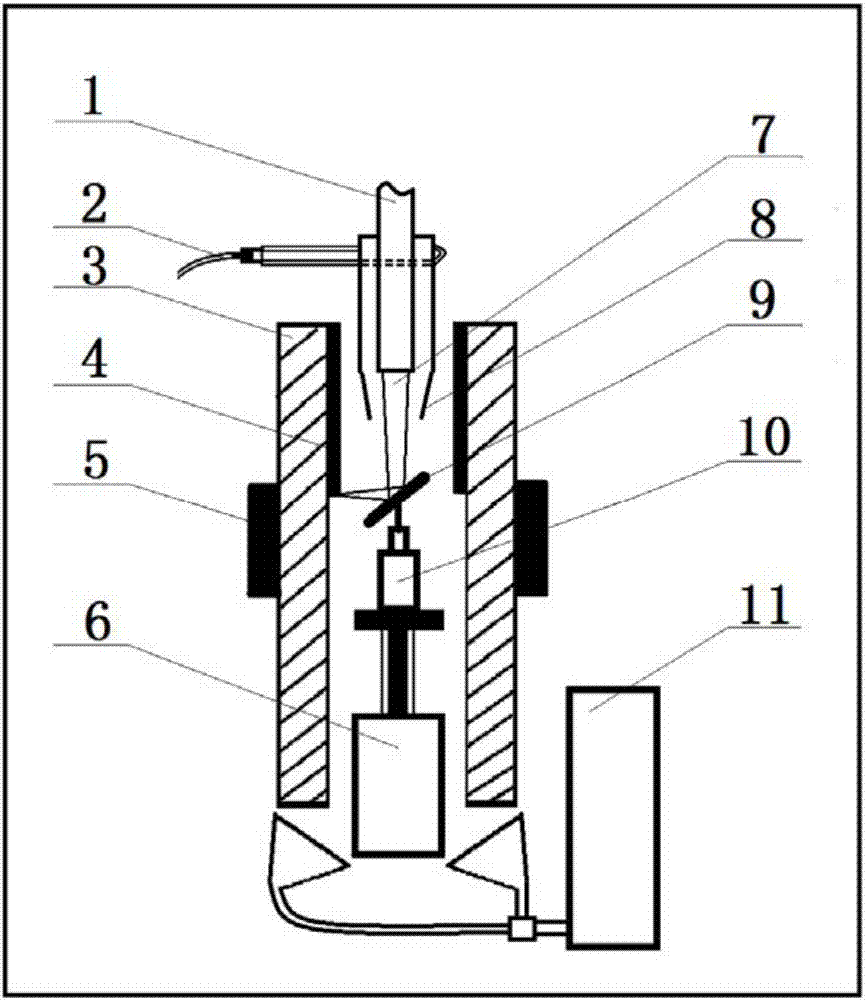
[0032] figure 1 It is a structural diagram of a laser cleaning device in Embodiment 1 of the present invention. This embodiment is applicable to situations where laser cleaning is required on the inner wall of a pipeline. refer to figure 1 , The laser cleaning device provided in this embodiment includes: a laser source 1, a gas nozzle 8, a gas delivery module 2, a mirror 9, a motor 10, an electric slide 6 and a smoke absorber 11;

[0033] The laser source 1 is used to emit a laser beam 7 toward the inner cavity of the pipeline 3 to be cleaned; the reflector 9 is used to reflect the laser beam 7 to the inner wall layer 4 of the pipeline 3 to be cleaned; the The gas delivery module 2 communicates with the gas nozzle 8 for delivering compressed gas to the inner cavity of the pipeline 3 to be cleaned through the gas nozzle 8;

[0034] The laser source 1, the gas nozzle 8 and the motor 10 are coaxially arranged, and the coaxial line coincides with the axis of the pipeline to be c...


PUM


Abstract

The invention discloses a laser cleaning device and method. The device includes a laser source, a gas nozzle, a gas conveying module, a reflector, a motor, an electric sliding table and a smog absorber; the laser source can emit the laser beam towards the inner cavity of a pipe to be cleaned; the reflector can reflect the laser beam to an inner wall layer to be cleaned; the gas conveying module is communicated with the gas nozzle for transferring compressed gas to the inner cavity of the pipe to be cleaned; the laser source, the gas nozzle and the motor are coaxially arranged, the coaxial line is overlapped with the axis of the pipe to be cleaned; the reflector is fixed on the motor; the motor is fixed on the electric sliding table and is rotated around the axis of the pipe to be cleaned; the electric sliding table is moved along the axis of the pipe to be cleaned; the gas nozzle fits the outer wall of the laser source; and the smog absorber is corresponding to the gas nozzle. The laser cleaning method and the method solve the problems that the existing laser cleaning device is difficult to operate when cleaning the inner wall of the pipe and the cleaning effect is poor, and realizes the purposes of simplifying cleaning of the inner wall of the pipe and improving the inner wall cleaning effect of the pipe.

Description

technical field [0001] The invention relates to laser cleaning technology, in particular to a laser cleaning device and method. Background technique [0002] Laser cleaning is an emerging surface treatment technology. It uses high-energy laser beams to irradiate the surface of the workpiece to be cleaned, so that the dirt, rust spots or coatings on the surface evaporate, gasify or peel off instantly, and effectively remove the attachments on the surface of the object at high speed. Or surface coating, so as to achieve the purpose of cleaning the surface of the workpiece. Laser cleaning has the advantages of good cleaning effect, high control precision, wide application range and low operating cost, so it has received more and more attention. [0003] When the existing laser cleaning device is applied to the cleaning of the inner wall of the pipeline, there are the following defects: on the one hand, since the laser source input end, the beam transmission system, the galvano...

Claims


Application Information

Patent Timeline
Patent Type & Authority Applications(China)
IPC IPC(8): B23K26/352B23K26/142B23K26/70
CPCB23K26/142B23K26/352B23K26/702B23K2101/06
Inventor 高文焱王军龙王学锋李广李本海薛亚飞闫贝贝张亚超
Owner BEIJING INST OF AEROSPACE CONTROL DEVICES
Why Eureka
Try Eureka