Eureka AIR delivers breakthrough ideas for toughest innovation challenges, trusted by R&D personnel around the world.

High-dryness dehydration device for thin layer sludge

A dehydration device and high-dryness technology, applied in water/sludge/sewage treatment, sludge treatment, dehydration/drying/concentrated sludge treatment, etc., can solve the problem of high cylinder pressure requirements, high sludge moisture content, easy There are many damaged parts and other problems, so as to improve the reliability and service life of the equipment, reduce the system configuration, and reduce the sealing requirements

Active Publication Date: 2017-07-07
CHINA JILIANG UNIV
View PDF3 Cites 7 Cited by
  • Summary
  • Abstract
  • Description
  • Claims
  • Application Information

AI Technical Summary

Problems solved by technology

[0010] In view of this, the present invention aims at the problems of many wearing parts, high energy consumption, high oil cylinder pressure requirements, and high moisture content of sludge after dehydration in the above-mentioned prior art, and proposes an , a thin-layer sludge high-dryness dehydration device with low sludge moisture content after dehydration

Method used


Image

  • High-dryness dehydration device for thin layer sludge
  • High-dryness dehydration device for thin layer sludge

Examples


Embodiment Construction

[0024] The present invention will be further described below in conjunction with the drawings and specific embodiments.

[0025] The present invention covers any alternatives, modifications, equivalent methods and solutions made on the essence and scope of the present invention. In order for the public to have a thorough understanding of the present invention, specific details are described in the following preferred embodiments of the present invention, and those skilled in the art can fully understand the present invention without the description of these details. In addition, for the sake of illustration, the drawings of the present invention are not drawn exactly according to the actual scale, and are described here.

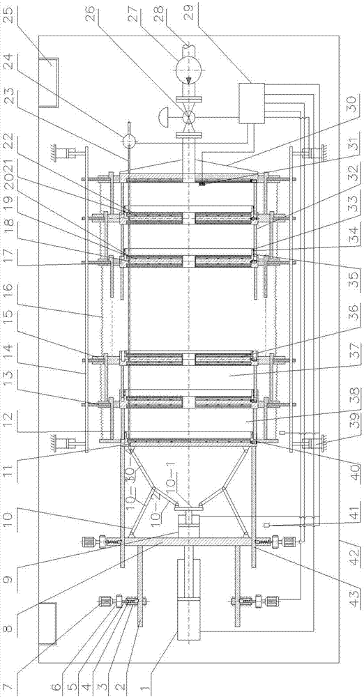
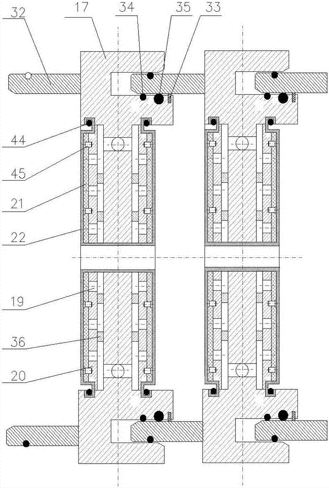
[0026] As shown in the figure, a thin-layer sludge high-dryness dehydration device of the present invention includes a filter press frame, a long-stroke cylinder 1, a short-stroke cylinder 9, a force amplification mechanism 10, a plate frame positioning and self-...


PUM


Abstract

The invention relates to a high-dryness dehydration device for thin layer sludge. The high-dryness dehydration device comprises a pressure filter plate frame, a long stroke oil cylinder (1), a short stroke oil cylinder (9), a force amplifying mechanism (10), a plate frame positioning and self-locking mechanism, a pressure filter cavity (37), a main push plate (8), an auxiliary push plate (11), a thrust plate (30), a high pressure sludge feed pump (28), a high pressure gas generator and components, and a rack (3), wherein the pressure filter plate frame comprises a filter frame (17) and a filter plate (20), and one side of the pressure filter plate frame is fixedly connected with an outer ring (32); a convex ring is also arranged at the other side of the pressure filter plate frame, and a sludge scraping ring, a first sealing piece and a second sealing piece are arranged on the convex ring; a circle of grooves is formed in the filter frame, and the adjacent filter plate frame, the outer ring (32), the convex ring and the sealing pieces form a volume-variable sealed chamber; the short stroke oil cylinder (9) and the force amplifying mechanism (10) are arranged between the main push plate (8) and the auxiliary push plate (11), and the main push plate (8) is fixedly connected with the long stroke oil cylinder.

Description

Technical field [0001] The invention relates to the field of sewage sludge treatment, in particular to a thin-layer sludge dehydration device with high dryness. Background technique [0002] The high moisture content of sludge is the bottleneck restricting the treatment and disposal of sludge. The sludge with high moisture content is not only bulky, but also contains a large amount of organic matter, heavy metals and harmful microorganisms that are easily corrupted or released into the environment, causing secondary pollution. The subsequent landfilling, incineration, and resource utilization of sludge will cause adverse effects. Therefore, the reduction of sludge deep dewatering is the primary purpose of sludge treatment, and reduction is the basis for achieving other "three transformations" of sludge. The drier the sludge, the more advantageous the subsequent treatment and disposal. [0003] In the early days, the commonly used dewatering equipment for sludge included plate and ...

Claims


Application Information

Patent Timeline
IPC IPC(8): C02F11/12C02F11/14
CPCC02F11/122C02F11/14
Inventor 饶宾期张岩卢锡龙万延见沈靖康
Owner CHINA JILIANG UNIV
Why Eureka
Eureka Blog
Learn More