

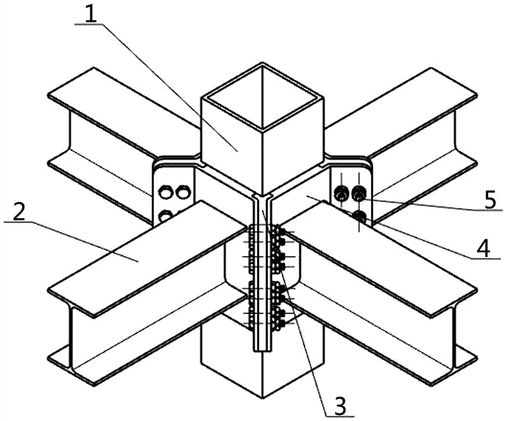
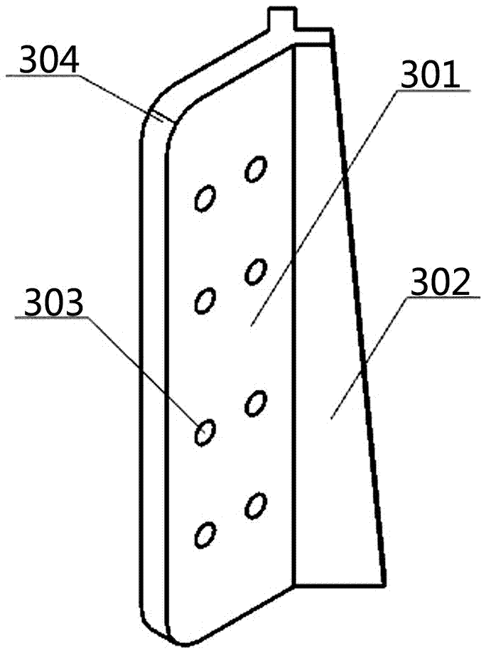
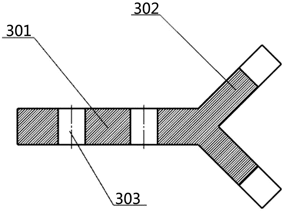
Nodes of Y-shaped double-lug square tubular column and H-shaped steel beam columns, connecting pieces and construction method
A technology of connectors and steel beams and columns, which is applied in the direction of construction and building construction, can solve the problems of difficult control of assembly accuracy, complicated construction methods, and poor universal interchangeability, so as to avoid slip stress and improve the installation accuracy of beams and columns and efficiency, and the effect of improving installation accuracy
- Summary
- Abstract
- Description
- Claims
- Application Information
AI Technical Summary
Problems solved by technology
Method used
Image

Examples
Embodiment Construction
[0042] Hereinafter, embodiments of a beam-column joint, fabricated connector and construction method of square steel and H-shaped steel of the present invention will be described with reference to the accompanying drawings.
[0043] The embodiments described herein are specific specific implementations of the present invention, which are used to illustrate the concept of the present invention. They are all explanatory and exemplary, and should not be construed as limiting the embodiments of the present invention and the scope of the present invention. In addition to the implementation exceptions described here, those skilled in the art can also adopt other obvious technical solutions based on the content disclosed in the claims and specification of this application. These technical solutions include adopting any obvious changes to the embodiments described herein. Technical solutions for replacement and modification.
[0044] The drawings in this specification are schematic diagram...
PUM
 Abstract
Description
Claims
Application Information