
Vibration power generating device and wind power generator with same

A technology of wind power generator and vibration power generation, which is applied to wind power generators, mechanisms for generating mechanical power, engines, etc. It can solve problems such as different structures, damage to wind power generator components, and loose connection parts, so as to increase power generation and absorb Vibration energy, vibration reduction effect

Inactive Publication Date: 2017-07-07
BEIJING PUHUA YINENG WIND POWER TECH
View PDF6 Cites 3 Cited by
  • Summary
  • Abstract
  • Description
  • Claims
  • Application Information

AI Technical Summary

Problems solved by technology

[0002] Existing wind turbines are often accompanied by severe vibration during the power generation process. This vibration will not only cause damage to the internal components of the wind turbine, but also the periodic vibration will easily cause the loosening of various connecting parts, making it necessary to equip maintenance Personnel regularly check the connection of each component to avoid serious accidents
Due to the inevitability of fan vibration, it is only possible to regularly reinforce the connection of the components to reduce the impact of vibration on the fan. However, vibration itself is also a kind of energy. Due to the different applications of existing vibration power generation equipment, its The structure is also very different. While the vibration power generation equipment uses vibration to generate electricity, it also acts as a shock absorber for the vibration source. However, due to the particularity of the fan structure, it is difficult to directly combine the existing vibration power generation equipment with the fan.

Method used


Image

  • Vibration power generating device and wind power generator with same
  • Vibration power generating device and wind power generator with same
  • Vibration power generating device and wind power generator with same

Examples


Embodiment 1

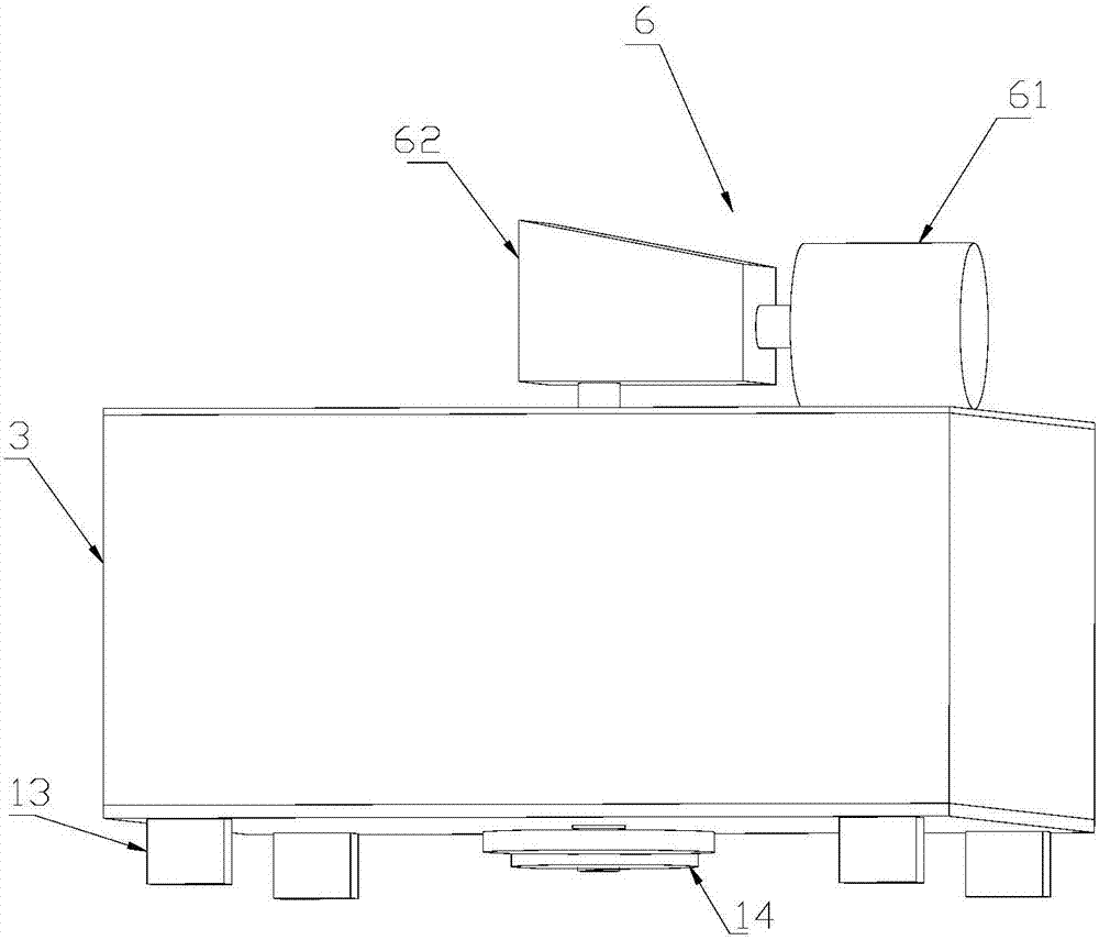
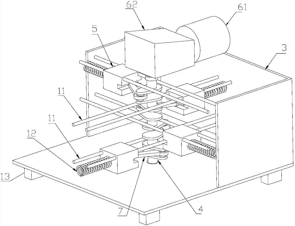
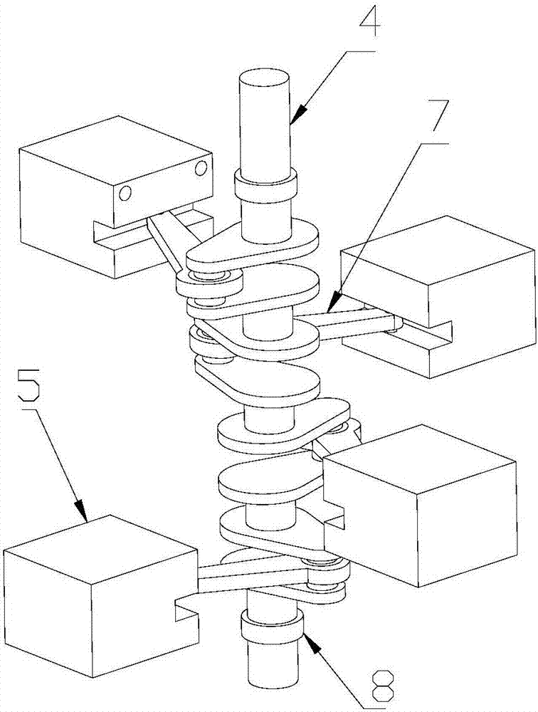
[0035] Such as figure 1 and figure 2 As shown, a vibration power generation device includes a box-shaped housing 3, an inertial element 5 movably arranged in the housing 3, a buffer device 12 connecting the inertial element 5 and the housing 3, and the two ends are opposite to each other. The housing 3 is rotatably connected to the crankshaft 4 connected to the inertial element 5 through the connecting rod 7, and the generator 6 is connected to one end of the crankshaft 4 and driven by the crankshaft 4 to generate electricity.

[0036] The housing 3 is fixedly mounted on the vibration source and vibrates synchronously with the vibration source. The inertial element 5 can freely reciprocate relative to the housing 3 in a horizontal direction. When the housing 3 vibrates with the vibration source, the inertia Due to the action of inertia, the element 5 has a motion tendency to keep still. The vibrating shell 3 and the inertial element 5 that remains stationary will move relati...

Embodiment 2

[0049] Such as Figure 5 And me Figure 6 As shown, the number of inertial elements 5 in this embodiment is two, and they are arranged at different heights along the axial direction of the crankshaft 4. The two inertial elements 5 are respectively located on both sides of the crankshaft 4, and the phase difference between the two is π / 2 radians, when one of the inertial elements 5 is in the dead point of motion, the other inertial element 5 has just passed the dead point, and pushes the crankshaft 4 to rotate in one direction under the action of inertial force, which can be effectively overcome by setting two inertial elements 5 A single inertial element 5 has the problem of motion dead point. This embodiment has a simple structure and is mainly applied to a vibration source with a single vibration direction.

Embodiment 3

[0051] Such as Figure 7 and Figure 8 As shown, in order to enable the vibration power generation device of the present invention to absorb vibration energy in multiple directions, the number of inertial elements 5 in this embodiment is four, and they are distributed on four front, rear, left and right sides of the crankshaft 4 accordingly. side, both ends of the crankshaft 4 are connected to the housing 3 through bearings 8, and one end extends to the outside of the housing 3 to connect with the power generation device 6; The axis is rotated at an angle of 90 degrees, and arranged in the order of left, right, rear, and front, that is, this embodiment adds a pair of inertial elements 5 on the basis of the second embodiment, and through a different arrangement from the first embodiment In this way, the starting torque can be reduced to achieve better power generation effect.


PUM


Abstract

The invention relates to a vibration power generating device. The vibration power generating device comprises a shell body, an inertia element, a crankshaft and a power generating device body, wherein the shell body is fixedly installed on a vibration source; the inertia element is movably arranged in the shell body; the crankshaft is rotationally installed on the shell body and connected with the inertia element through a connecting rod; and the power generating device body is connected with one end of the crankshaft and is driven to generate power by the crankshaft. The invention further relates to a wind power generator with the vibration power generating device. On the one hand, the vibration power generating device is made to work through vibration of the wind power generator, and electric energy is generated; and on the other hand, vibration reducing is conducted on the wind power generator through the energy absorption effect of the vibration power generating device, so that the purpose of reducing vibration of the wind power generator is achieved.

Description

technical field [0001] The invention relates to a power generating device, in particular to a vibration power generating device and a wind power generator equipped with the device. Background technique [0002] Existing wind turbines are often accompanied by severe vibration during the power generation process. This vibration will not only cause damage to the internal components of the wind turbine, but also the periodic vibration will easily cause the loosening of various connecting parts, making it necessary to equip maintenance Personnel regularly check the connection of various components to avoid serious accidents. Due to the unavoidable vibration of the fan, it is only possible to regularly reinforce the connection of the components to reduce the impact of the vibration on the fan. However, the vibration itself is also a kind of energy. Due to the different application occasions of the existing vibration power generation equipment, its The structure is also very diffe...

Claims


Application Information

Patent Timeline
Patent Type & Authority Applications(China)
IPC IPC(8): F03G7/08F03D80/00
CPCF03G7/08F05B2260/96Y02E10/72
Inventor 张羽鲁志平刘峰张磊冯克瑞马泳吏
Owner BEIJING PUHUA YINENG WIND POWER TECH
Learn More