
Fluid control valve and control method thereof

A fluid control valve and control method technology, applied in the direction of flow control, control/regulation system, non-electric variable control, etc., can solve the problems of fluid control valve blockage, failure to judge the valve body, etc., to eliminate precision errors and improve the use of Convenience, the effect of eliminating misunderstandings

Active Publication Date: 2017-07-07
HORIBA STEC CO LTD
View PDF8 Cites 0 Cited by
  • Summary
  • Abstract
  • Description
  • Claims
  • Application Information

AI Technical Summary

Problems solved by technology

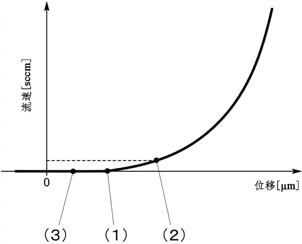
[0008] Therefore, if the user confirms the position of the valve body only by the output of the position sensor, it is impossible to judge whether the valve body has actually passed the opening position.

Method used


Image

  • Fluid control valve and control method thereof
  • Fluid control valve and control method thereof
  • Fluid control valve and control method thereof

Examples


Embodiment Construction

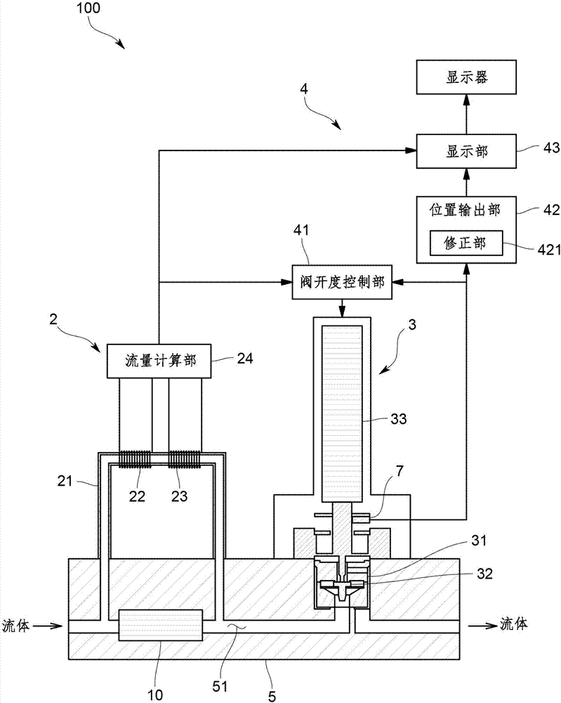
[0034] Hereinafter, an embodiment of a mass flow controller incorporating the fluid control valve of the present invention will be described with reference to the drawings.

[0035] The mass flow controller 100 of this embodiment is used, for example, in a semiconductor manufacturing process.

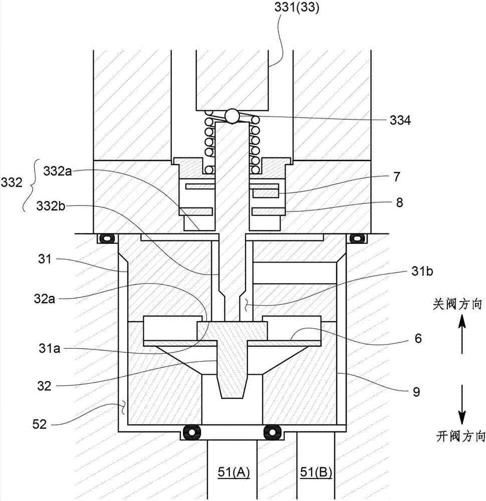
[0036] Specifically, such as figure 1 As shown, the mass flow controller 100 includes: a main body 5 formed with a flow channel 51, for example, a fluid such as a gas for semiconductor processing flows through the flow channel 51; a flow measuring mechanism 2, which measures the flow through the flow channel 51 The flow rate of the fluid; the fluid control valve 3, which controls the flow rate of the fluid flowing through the flow passage 51; and the control device 4, which controls the valve opening of the fluid control valve 3, so that the flow measurement mechanism 2 outputs the measured flow rate Close to the predetermined set flow. Hereinafter, each part is described in detail.

[0037...


PUM


Abstract

The present invention provides a fluid control valve that improves usability by eliminating misunderstanding of a user, and a control method thereof. The fluid control valve includes a valve seat (31), a valve body (32) disposed to be approachable to and separable from the valve seat (31), an actuator (33) configured to move the valve body (32) in an approaching or separating direction, a positional information detection part (7) configured to detect a value corresponding to a relative position of the valve body (32) with respect to the valve seat (31), and a position output part (42) configured to set, irrespective of positional information acquired by the positional information detection part (7) at an opening start position of the valve body (32), the opening start position to position zero.

Description

Technical field [0001] The present invention relates to a fluid control valve for controlling the flow rate and pressure of a fluid and a control program for the fluid control valve. Background technique [0002] As shown in Patent Document 1, a conventional fluid control valve includes: a valve seat; a valve body provided so as to be able to approach or leave the valve seat; and an actuator to move the valve body. The fluid control valve is used for controlling such that the opening degree between the valve seat and the valve body is adjusted by the actuator so that the flow rate and pressure of the fluid become target values. [0003] As shown in Patent Document 2, there is a fluid control valve having a position sensor that measures the position of the valve body relative to the valve seat among the fluid control valves. The fluid control valve performs position control using the position of the valve body obtained by the position sensor. As a result, it is possible to control...

Claims


Application Information

Patent Timeline
Patent Type & Authority Applications(China)
IPC IPC(8): F16K31/02F16K37/00
CPCF16K31/02F16K37/0025F16K37/0041Y10T137/8242F16K31/007F16K37/0083F16K37/0091G05D7/0635F16K1/34G05D7/0617G01D3/022F16K1/12
Inventor 国田大地家城笃史
Owner HORIBA STEC CO LTD
Learn More