Radio frequency coil unit for magnetic resonance imaging and radio frequency coil

A magnetic resonance imaging and radio frequency coil technology, applied in magnetic resonance measurement, measurement of magnetic variables, measurement devices, etc., to achieve the effect of increasing series impedance, improving inter-unit coupling, and reducing coupling degree

Active Publication Date: 2017-07-07
SUZHOU MEIKE MEDICAL TECH CO LTD
View PDF4 Cites 11 Cited by
  • Summary
  • Abstract
  • Description
  • Claims
  • Application Information

AI Technical Summary

Problems solved by technology

[0048] The purpose of the present invention is: to propose a radio frequency coil unit and a radio frequency coil for magnetic resonance imaging, to effectively solve the coupling between coil units, parallel transmission performance, transmission Field Uniformity and Receive Penetration Issues

Method used


Image

  • Radio frequency coil unit for magnetic resonance imaging and radio frequency coil
  • Radio frequency coil unit for magnetic resonance imaging and radio frequency coil
  • Radio frequency coil unit for magnetic resonance imaging and radio frequency coil

Examples


Embodiment 1

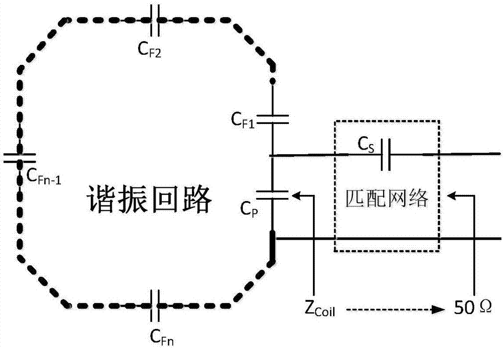
[0104] Figure 10 It shows the first specific embodiment of the radio frequency coil unit for magnetic resonance imaging (hereinafter referred to as the coil unit) of the present invention, which is the same as the traditional radio frequency coil unit in that it also includes a resonant circuit and a matching network connected to each other . Among them, the resonant tank is composed of multiple (n) capacitors ( Figure 10 specifically shown in the C p 、C F1 、C F2 、C Fn-1 and C Fn 5 capacitors that form a resonant circuit) are connected in series to form a closed circuit through a conductor (the conductor is usually a copper wire). The matching network consists of a capacitor C S constitute.

[0105] The key improvement of this embodiment is that an active lossy circuit is additionally provided in the radio frequency coil unit, and the function of the active lossy circuit is to actively consume and absorb the radio frequency power in the radio frequency coil unit (tha...

Embodiment 2

[0115] Figure 11 A second specific embodiment of the radio frequency coil unit for magnetic resonance imaging of the present invention is shown, which also includes a resonant circuit and a matching network connected to each other. Among them, the resonant tank is composed of multiple capacitors ( Figure 11 specifically shown in the C p 、C F1 、C F2 、C Fn-1 and C Fn 5 capacitors that form a resonant circuit) are connected in series to form a closed circuit through a conductor (the conductor is usually a copper wire). The matching network consists of a capacitor C S constitute.

[0116] Same as Embodiment 1, an active lossy circuit R for actively consuming and absorbing the radio frequency power in the radio frequency coil unit to reduce the Q value of the radio frequency coil unit is specially set in the radio frequency coil unit LOSS .

[0117] The difference from Embodiment 1 is that there is only one active lossy circuit in this embodiment, and the active lossy ci...

Embodiment 3

[0120] Figure 12 A third specific embodiment of the radio frequency coil unit for magnetic resonance imaging according to the present invention is shown, which also includes a resonant circuit and a matching network connected to each other. Among them, the resonant tank is composed of n capacitors ( Figure 12 specifically shown in the C p 、C F1 、C F2 、C Fn-1 and C Fn 5 capacitors that form a resonant circuit) are connected in series to form a closed circuit through a conductor (the conductor is usually a copper wire). The matching network consists of a capacitor C S constitute.

[0121] Same as the second embodiment, an active lossy circuit R for actively consuming and absorbing the radio frequency power in the radio frequency coil unit to reduce the Q value of the radio frequency coil unit is specially set in the radio frequency coil unit LOSS . And the active lossy circuit R LOSS Set it away from the resonant tank and connect it away from the resonant tank.

[0...


PUM


Abstract

The present invention discloses a radio frequency coil unit for magnetic resonance imaging and a radio frequency coil. The radio frequency coil unit is connected with an active loss circuit capable of actively consuming and absorbing radio frequency power in the radio frequency coil unit to decrease the Q value of the radio frequency coil unit. According to the radio frequency coil unit for magnetic resonance imaging and the radio frequency coil of the invention, the active loss circuit is introduced into the coil unit; the active loss circuit can be utilized to absorb the radio frequency power in the radio frequency coil unit to decrease the Q value of the radio frequency coil unit, and therefore, the coupling degree (correlation coefficient) of every two units in an array coil composed of radio frequency coil unit groups can be decreased, and parallel transmission (PTX) performance can be improved, and the uniformity of a magnetic resonance radio frequency transmitting field can be also improved.

Description

technical field [0001] The invention belongs to the field of magnetic resonance imaging, and in particular relates to a radio frequency coil unit and a radio frequency coil for magnetic resonance imaging. Background technique [0002] Radio Frequency (RF, Radio Frequency) coil is a key component of the magnetic resonance system, and the performance of the coil has a great impact on the overall performance, safety and image quality of magnetic resonance products. The radio frequency coil is responsible for the excitation and acquisition of magnetic resonance signals in the MRI system. The radio frequency excitation field (B1 Field) is generated by the radio frequency transmitting coil, which is opposed to the atomic nucleus containing the sample whose spin is not zero in the fixed main magnetic field (B0Field) ( The most commonly used hydrogen nucleus) is excited to generate a nuclear magnetic resonance (NMR) signal, and then the receiving coil receives and collects the magne...

Claims


Application Information

Patent Timeline
Patent Type & Authority Applications(China)
IPC IPC(8): G01R33/36
CPCG01R33/365G01R33/3628G01R33/5612G01R33/3415G01R33/3671G01R33/34092G01R33/3621G01R33/3664
Inventor 朱华彬
Owner SUZHOU MEIKE MEDICAL TECH CO LTD
Why Eureka
Try Eureka