A video signal amplifier

A video signal and amplifier technology, applied in the field of video signal amplifiers, can solve the problems of large video signal amplifiers, poor anti-electromagnetic interference performance, unfavorable docking installation, etc., to achieve strong anti-electromagnetic interference performance, fast installation and debugging, and convenient installation and maintenance Effect

Active Publication Date: 2019-12-13
GUIZHOU AEROSPACE ELECTRONICS TECH CO LTD
View PDF8 Cites 0 Cited by
  • Summary
  • Abstract
  • Description
  • Claims
  • Application Information

AI Technical Summary

Problems solved by technology

[0004] According to the existing scheme, there will be the following defects: 1. Using one printed board, the strong and weak signals are all concentrated on one printed board, which is easy to cause self-excited oscillation, and the anti-electromagnetic interference performance is poor; 2. Using a printed circuit board The board is installed flat in the cavity. For the convenience of installation and operation, the required space is large, resulting in a large video signal amplifier, which is not conducive to the docking installation with other electronic equipment; 3. SMA connectors are used as communication interfaces. The installation method of the SMA type connector is in the form of a screw fastening flange, so it occupies a large volume; 4. After the video amplifier is installed in other electronic equipment, the sensitivity generally needs to be adjusted, so the gain of the video amplifier needs to be adjusted to meet the signal output requirements.
However, the existing video signal amplifier needs to open the cover to debug, which is extremely inconvenient to operate and has low work efficiency.

Method used


Image

  • A video signal amplifier
  • A video signal amplifier
  • A video signal amplifier

Examples


Embodiment Construction

[0023] The technical solution of the present invention is further described below, but the scope of protection is not limited to the description.

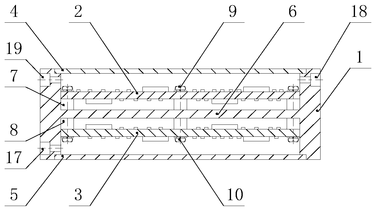
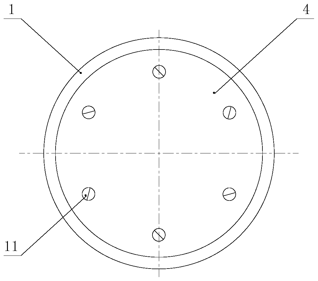
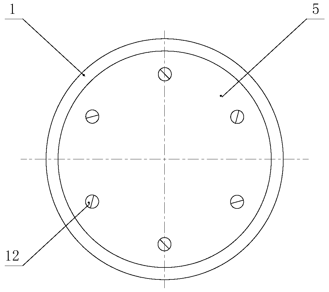
[0024] Such as Figure 1 to Figure 4 A video signal amplifier shown includes a cavity 1, a printed board I2, a printed board II3, an upper cover 4, and a lower cover 5; the upper and lower hollows of the cavity 1 are two cavities, and the cavity There is a partition 6 in the middle of the body, and an upper boss 7 and a lower boss 8 are respectively arranged on the top and bottom of the partition 6; the upper cover 4 and the lower cover 5 cover the cavity 1 and adopt a step overlapping method , fastened with upper screws 11 and lower screws 12; the printed board I2 is installed on the upper boss 7 in the cavity 1 and fastened with screws 9, and the printed board II3 is installed on the lower boss in the cavity 1 8 and fastened with screws 10; the side of the cavity 1 is provided with a first J-SMP connector 17, a second J-SMP conn...


PUM


Abstract

The invention provides a video signal amplifier, comprising a cavity, a printed board I, a printed board II, an upper cover board and a lower cover board. The upper part and the lower part of the cavity are hollow and form an upper hollow cavity and a lower hollow cavity. A clapboard is arranged in the middle of the cavity. An upper boss and a lower boss are respectively arranged above and below the clapboard. The upper cover board and the lower cover board seal the cavity, are in a step lapping mode and are fastened through an upper bolt and a lower bolt. The printed board I is mounted on the upper boss in the cavity and is fastened by a bolt. The printed board II is mounted on the lower boss in the cavity and is fastened by the bolt. A first J-SMP connector, a second J-SMP connector and a third J-SMP connector are arranged on the side faces of the cavity. The first J-SMP connector is connected with the printed board II. The second J-SMP connector and the third J-SMP connector are connected with the printed board I. According to the video signal amplifier, the mounting is convenient, an occupied space is very small, the operability is high, the anti-electromagnetic interference performance is high, a size is small, a structure is compact, the mounting and debugging are rapid, and the mounting and maintenance are convenient.

Description

technical field [0001] The invention relates to a video signal amplifier. Background technique [0002] At present, video signal amplifiers have been widely used and popularized in many fields such as electronics, communication, automatic control, and aerospace. [0003] The existing video signal amplifier is used to amplify the video input signal within a certain dynamic range to a digital signal with a certain intensity, and output it to a digital signal processor. The existing video signal amplifier is structurally composed of a cavity, a printed board, and a cover plate. The printed board is flatly installed in the cavity and packaged with a cover plate, and an SMA type connector is installed on the outside to input and output signals. [0004] According to the existing scheme, there will be the following defects: 1. Using one printed board, the strong and weak signals are all concentrated on one printed board, which is easy to cause self-excited oscillation, and the an...

Claims


Application Information

Patent Timeline
Patent Type & Authority Patents(China)
IPC IPC(8): H04N5/14
CPCH04N5/148
Inventor 刘小玲
Owner GUIZHOU AEROSPACE ELECTRONICS TECH CO LTD
Why Eureka
Try Eureka