Vegetable seedling close planting machine
A vegetable and seed technology, applied in the field of agricultural machinery and tools, can solve the problems of fast and efficient planting, and achieve the effect of simple structure, convenient operation, and reduced mutual entanglement
- Summary
- Abstract
- Description
- Claims
- Application Information
AI Technical Summary
Problems solved by technology
Method used
Image
Examples
Embodiment 1
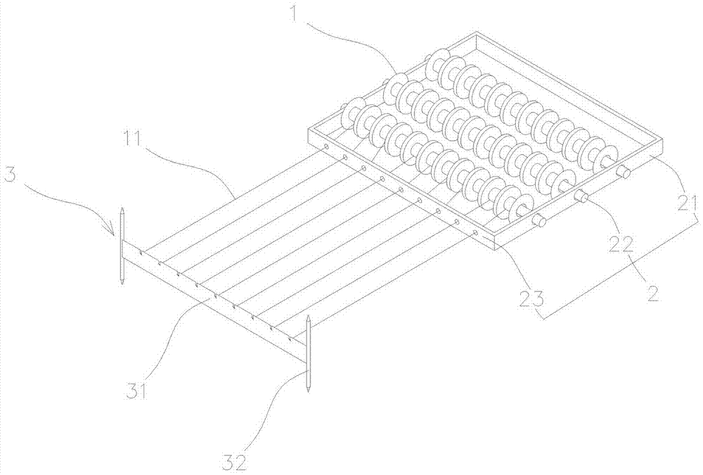
[0038] Such as figure 1 This embodiment includes a reel 1, a reel holder 2, and a positioner 3. The reel 1 is wrapped with a seed webbing 11, the reel holder 2 is used to install and fix the reel 1, and the positioner 3 is used to fix the seed webbing 11 The beginning of
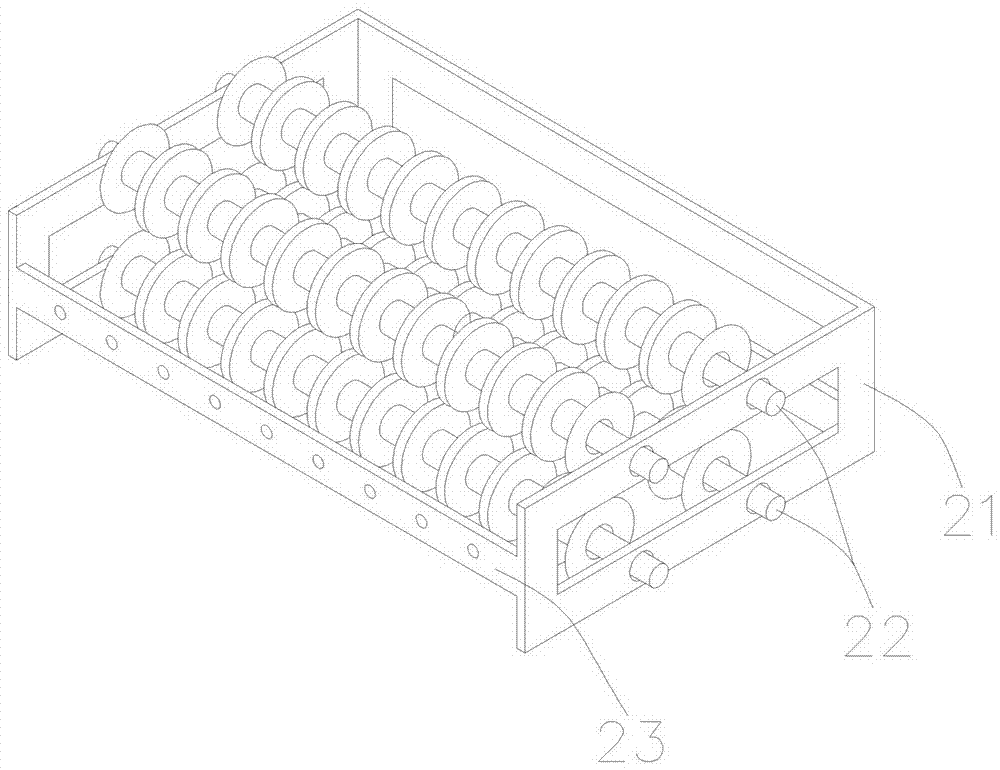
[0039] The reel frame 2 includes a support 21, a shaft 22, and an orifice 23. The support 21 has a rectangular frame structure. The shaft 22 is movably connected to the two sides of the support 21, and the reel 1 is movably sleeved on the shaft 22. , And can rotate freely on the shaft 22; the front end of the bracket 21 is an orifice plate 23, the orifice plate 23 is a long strip, there are several holes on it, used to pass the seed webbing 11 out of it; the hole of the orifice plate 23 The spacing is 2~3.5 cm, preferably 2.5 or 3 cm, so that there is enough space for seedling growth;
[0040] The positioner 3 includes a wire plate 31 and a fixing rod 32. The wire plate 31 is a long strip. There are several groo...
Embodiment 2
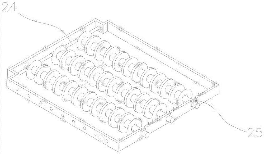
[0044] Such as image 3 On the basis of the above-mentioned embodiment, the reel frame 2 described in this embodiment is provided with a rotating rod 24 on one side of the support 21, two ends of the rotating rod 24 are mounted on the support 21, and one end of the shaft 22 is hinged on the rotating rod 24, The other end is restricted to the support 21 by a groove on the support 21, and a lock 25 is provided on the groove at one end of the restricting shaft 22 on the support 21. The shaft 22 hinged at one end and movably connected at the other end can facilitate the operation of taking and releasing the reel 1 on the shaft 22, which improves the work efficiency; the movably connected end of the shaft 22 can be restricted in the groove of the bracket 21, or Setting a stop on the bracket 21, or any other known limiting method, can be used to locate the movable end of the shaft 22; in addition, the positioning device at the movable end of the shaft 22 should usually be provided wit...
Embodiment 3
[0046] Such as Figure 4 On the basis of the above embodiment, the orifice plate 23 in this embodiment is detachable to facilitate the replacement of orifice plates 23 with different hole pitches. The detachable orifice plate 23 has a limit structure and a buckle matching the bracket 21 at both ends and / or bottom end, so that the orifice plate 23 can be fixedly installed on the bracket 21, and it is convenient to replace the orifice plates 23 of different specifications. .
[0047] Further, as Figure 5 The orifice plate 23 is a split type, and the orifice plate 23 is divided into upper and lower parts that are fastened to each other along the hole to facilitate the penetration of the seed webbing 11. The upper and lower parts of the orifice plate 23 can be separated along the middle of the hole, or can be knitted and separated, so that the lower part has a relatively larger hole to facilitate the insertion of the seed webbing 11. After the seed webbing 11 is put into the hole, ...
PUM
 Abstract
Description
Claims
Application Information
 - R&D
- Intellectual Property
- Life Sciences
- Materials
- Tech Scout
- Unparalleled Data Quality
- Higher Quality Content
- 60% Fewer Hallucinations
Browse by: Latest US Patents, China's latest patents, Technical Efficacy Thesaurus, Application Domain, Technology Topic, Popular Technical Reports.
© 2025 PatSnap. All rights reserved.Legal|Privacy policy|Modern Slavery Act Transparency Statement|Sitemap|About US| Contact US: help@patsnap.com


