Intelligent biliary tract pressure detecting device

A manometry device and biliary tract technology, which can be used in telemetry patient monitoring, diagnostic recording/measurement, medical science, etc., can solve problems such as bile reflux, drainage tube height influence, and inaccurate detection, and achieve accurate bile pressure.

Pending Publication Date: 2017-07-14
WENZHOU CENT HOSPITAL
0 Cites 1 Cited by

AI-Extracted Technical Summary

Problems solved by technology

[0004] However, the existing methods of measuring biliary pressure all extend into the biliary tract through a drainage tube, draw out the bile in the biliary tract and flow into the U-shaped tube for detection, and effectively indicate the current situation through the scale on the U-shaped tube. Bile pressure of the biliary tract, but this method of measuring bile pressu...

Method used

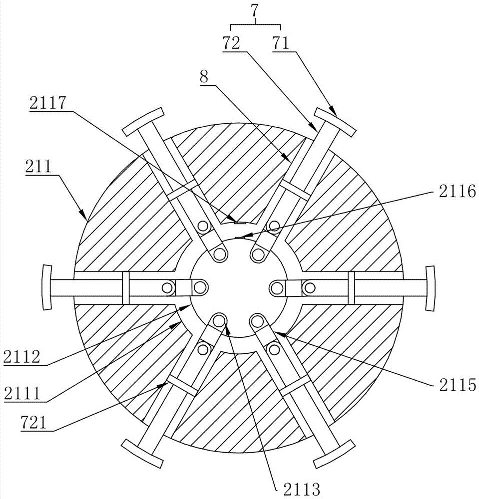
As a kind of specific embodiment of improvement, the outer side wall of described connection plate 211 is provided with fixed leg 7, and described fixed leg 7 is used for conflicting with biliary tract inner wall, to be fixed in biliary tract with connection plate 211, The fixed leg 7 includes a foot portion 71 and a rod portion 72, the foot portion 71 is fixed on one end of the rod portion 72, and the outer side wall of the connecting plate 211 is provided with a drive channel 8 extending toward the center of the connecting plate 211 Inside, the other end of the rod portion 72 relative to the foot portion 71 is slidably inserted into the drive channel 8 on the outer wall of the connection plate 211, and the drive channel 8 has a retracted position and an extended position. When the rod portion When the end of the rod 72 slides to the retracted position, the rod 72 retracts into the drive channel 8, and the foot 71 is attached to the outer side wall of the connection plate 211. When the end of the rod 72 slides to the extended position, the rod Part 72 protrudes outward from the driving channel 8, and the foot portion 71 is in conflict with the inner wall of the biliary tract, so that the connection plate 211 is fixed in the biliary tract. When testing, the fixed leg 7 is opened as shown in Figure 3, and the fixed leg 7 is opened. The feet 71 of the feet are in conflict with the inner wall of the biliary tract, so that an effect of positioning the connecting plate 211 in the biliary tract can be achieved, so that in the process of detecting the bile pressure, the pressure sensor caused by the shaking of the connecting plate 211 and the pressure sensor 212 can be avoided. The problem that the pressure exerted by the bile detected by 212 changes, which makes the detection of bile pressure more accurate, and through the setting of the driving channel 8 and the rod 72, it can be realized that during the process of extending into the biliary tract, the foot 71 It can be stowed as shown in Figure 4...

Abstract

The invention discloses an intelligent biliary tract manometry device, which comprises a tube body and a detection head arranged at the end of the tube body. The end of the tube body provided with the detection head extends into the biliary tract. The detection head includes a shell and A detection circuit arranged in the casing, the casing includes a connection plate connected to the end of the pipe body and a pressure sensor fixed on the end surface of the connection plate facing away from the pipe body, the pressure sensor is coupled to the detection circuit, The detection circuit includes: a wireless communication circuit coupled to the pressure sensor; a button battery coupled to the wireless communication circuit and the pressure sensor for powering the wireless communication circuit and the pressure sensor. The intelligent biliary tract manometry device of the present invention can effectively set the detection head in the biliary tract through the tube body through the arrangement of the tube body and the detection head at the end of the tube body, and then use the detection head to detect the bile pressure, which is convenient There is no need to draw out the bile, avoiding a series of problems.

Application Domain

CatheterSensors +1

Technology Topic

EngineeringPressure sensor +3

Image

  • Intelligent biliary tract pressure detecting device
  • Intelligent biliary tract pressure detecting device
  • Intelligent biliary tract pressure detecting device

Examples

  • Experimental program(1)

Example Embodiment

[0032] As an improved specific implementation manner, the wireless communication circuit 221 includes a wireless transmitting circuit and a wireless receiving circuit, and the wireless transmitting circuit includes:
[0033] The wireless transmitting antenna 2211, the wireless transmitting antenna 2211 is coupled to the pressure sensor 212 and the power supply, the wireless transmitting antenna 2211 is also coupled to the capacitor C and grounded;
[0034] A crystal oscillator J, one end of the crystal oscillator J is coupled to the other end of the pressure sensor 212 coupled to the wireless transmitting antenna 2211, and the other end of the crystal oscillator J is grounded;
[0035] The wireless receiving circuit includes:
[0036] The wireless receiving antenna 2212 is grounded after being coupled to the inductor L;
[0037] The XOR gate U has a first input terminal, a second input terminal and an output terminal. The second input terminal is coupled to the node between the inductor L and the wireless receiving antenna 2212. The output terminal The transistor Q is coupled to the electromagnet 2116, the base of the triode Q is coupled to the output terminal of the XOR gate U, the collector is coupled to the power supply, and the emitter is coupled to the electromagnet 2116 and then grounded;
[0038] A crystal oscillator Z, one end of the crystal oscillator Z is coupled to the power supply, and the end is also coupled to the first input end of the XOR gate U, the other end of the crystal oscillator Z is grounded, and the capacitor C1 is also coupled to the XOR gate The first input terminal of U is coupled. During the working process of the wireless communication circuit 221, the wireless transmitting circuit and the wireless receiving circuit will work first. During the working process of the wireless transmitting circuit, the crystal oscillator J will oscillate and output an oscillation. The signal is sent to the capacitor C and the pressure sensor 212, so that the capacitor C will be sequentially charged and discharged by the pressure sensor 212 according to the oscillation signal of the crystal oscillator J to convert the oscillation signal into a sine wave signal and input it into the wireless transmitting antenna 2211. The wireless transmitting antenna 2211 will transmit this sine wave signal. The charging and discharging speed of the capacitor C is determined by the output resistance of the pressure sensor 212, so that when the output resistance of the pressure sensor 212 changes, The duty cycle of the sine wave signal also changes. In this way, by calculating the duty cycle of the received sine wave signal, the output resistance of the pressure sensor 212 can be effectively obtained. This is a good realization of the pressure sensor 212 The output resistance is transmitted wirelessly. When the external device sends a wireless signal to drive the electromagnet 2116 to open the foot 71, the external wireless sine wave signal will be received through the wireless receiving antenna 2212 and the inductor L After the stable, the sine wave signal formed by the combination of the crystal oscillator Z and the capacitor C1 is input into the XOR gate U, because the XOR gate U is only output when the signals at the first input terminal and the second input terminal are exactly the same. 1, which means that when the sine wave signal received by the wireless receiving antenna 2212 is equal to the sine wave signal produced by the crystal oscillator Z and the capacitor C1, 1 will be output, so that it can effectively realize that an external device can send a signal to the crystal oscillator Z and The capacitor C1 cooperates with the sine wave signal to generate the same sine wave signal to realize the driving transistor Q is turned on, thereby making the electromagnet 2116 work, so that the effect of a wireless communication control electromagnet 2116 is realized. This embodiment The same-OR gate chip model used in is 74HC136 and other chips.
[0039] In summary, the intelligent biliary tract pressure measuring device of this embodiment can extend the detection head 2 into the biliary tract through the setting of the tube body 1, and the pressure sensor 212 and the detection circuit 22 can effectively detect The effect of reaching the bile pressure in the biliary tract and outputting the bile pressure signal wirelessly, so that a good effect of detecting the bile pressure in the biliary tract is realized, and at the same time, the bile is not required to be drawn out during the detection process. This avoids a series of problems in the prior art.

PUM

no PUM

Description & Claims & Application Information

We can also present the details of the Description, Claims and Application information to help users get a comprehensive understanding of the technical details of the patent, such as background art, summary of invention, brief description of drawings, description of embodiments, and other original content. On the other hand, users can also determine the specific scope of protection of the technology through the list of claims; as well as understand the changes in the life cycle of the technology with the presentation of the patent timeline. Login to view more.
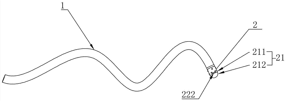
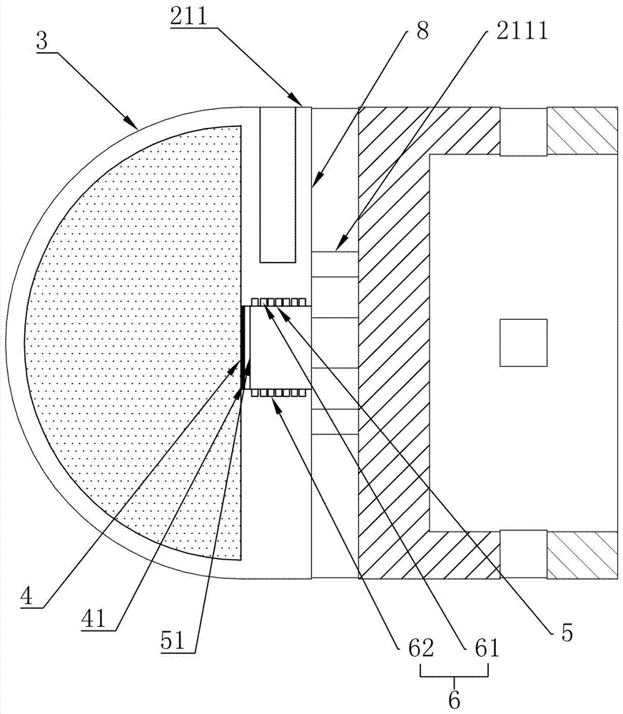
Why Eureka
Try Eureka