Wireless-power type termite detection system

A wireless power supply and detection system technology, applied in radio wave measurement system, electromagnetic wave system, electric/magnetic exploration, etc., can solve problems such as unusable and insufficient power, achieve low false alarm rate, long service life, and applicable wide range of effects

Inactive Publication Date: 2015-12-23
ZHEJIANG DEKAN ENVIRONMENT TECH CO LTD
View PDF5 Cites 7 Cited by
  • Summary
  • Abstract
  • Description
  • Claims
  • Application Information

AI Technical Summary

Problems solved by technology

[0005] The present invention aims at the problems existing in the above-mentioned prior art, and proposes a termite detection system with wireless power supply. Its wireless power supply solves the problem that the existing termite detection system is always powered on, and there may be insufficient power, resulting in unusable problems

Method used


Image

  • Wireless-power type termite detection system
  • Wireless-power type termite detection system
  • Wireless-power type termite detection system

Examples


Embodiment 1

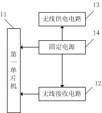
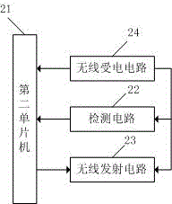
[0044] combine Figure 1-2 , this implementation describes in detail the wireless powered termite detection system of the present invention, which includes: a first circuit board and a second circuit board. Wherein: the first circuit board is arranged on the termite detection detector, and its schematic diagram is as follows figure 1 As shown, it includes: a first single-chip microcomputer 11, a wireless receiving circuit 12, a wireless power supply circuit 13 and a fixed power supply 14; The wireless power supply circuit 13 is also connected to the wireless receiving circuit 12. The second circuit board is arranged on the termite detection unit, and its schematic diagram is as follows figure 2 As shown, it includes: a second single-chip microcomputer 21, a detection circuit 22, a wireless transmitting circuit 23 and a wireless power receiving circuit 24; The electric circuit 24 is also connected with the detection circuit 22 and the wireless transmission circuit 23 . The...

Embodiment 2

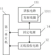
[0047] Such as image 3 Shown is a schematic diagram of the first circuit board of this embodiment. This embodiment is based on Embodiment 1. The wireless power supply circuit 13 includes a resonant circuit 131, and the resonant circuit 131 includes a transmitting coil 1311. The wireless power supply circuit 13 passes the resonant The circuit 131 is connected with the first single chip microcomputer 11 and the wireless receiving circuit 12 .

Embodiment 3

[0049] Such as Figure 4 Shown is a schematic diagram of the first circuit board of this embodiment, which is based on the second embodiment, adding an LED indicating circuit 15 , a sound indicating circuit 16 and a data storage circuit 17 on the first circuit board.

[0050] Such as Figure 5 Shown is the pin diagram of the first single-chip microcomputer 11, the model of the first single-chip microcomputer 11 adopted in this embodiment is MCU: STM8S207.

[0051] Such as Image 6 Shown is the circuit diagram of the wireless receiving circuit 12 and the wireless power supply circuit 13, the wireless power supply circuit 13 provides 3.3V voltage to the first single-chip microcomputer 11 and the data storage circuit 17 through a simple voltage stabilizing circuit; the wireless power supply circuit 13 is the first single-chip microcomputer 11 The power supply is 3.3V, and the wireless receiving circuit 12 is powered by 5V, so R3 is used as data level conversion; the wireless re...


PUM


Abstract

The invention discloses a wireless-power type termite detection system comprising a first circuit board and a second circuit board. The first circuit board arranged on a termite detection device consists of a first single-chip microcomputer, a wireless receiving circuit, a wireless power supply circuit and a fixed power supply. The second circuit board arranged on a single termite detection body includes a second single-chip microcomputer, a detecting circuit, a wireless transmitting circuit and a wireless power-receiving circuit. The wireless power supply circuit and a wireless power-receiving circuit are connected wirelessly. The wireless power supply circuit is used for providing power for the first single-chip microcomputer, the wireless receiving circuit, and the second circuit board; and the wireless receiving circuit is used for receiving a signal transmitted by the wireless transmitting circuit. According to the wireless-power type termite detection system, the circuit board with the single termite detection body is not electrified when no detection is carried out; and when detection needs to be carried out, the circuit board is powered wirelessly. The application range is wide and the service life is long.

Description

technical field [0001] The invention relates to the field of termite control, in particular to a termite detection wireless power supply detection system. Background technique [0002] Termites are one of the five major pests in the world, especially in tropical and subtropical regions. Termites can eat all plants, and the formic acid secreted in their bodies can also corrode steel bars and denature concrete. Termites have brought a lot of damage to people's daily life, including damage to buildings, dams, crops, books, underground cables, etc. [0003] In addition, the damage caused by termites is concealed. For example, the damage caused by termites to buildings, especially to brick and wood structures and wooden structures, is often hidden inside the structure. Holes often cause the collapse of houses, resulting in property damage and casualties. [0004] For a long time, the method of preventing and controlling termites is drug prevention, applying insecticides in the...

Claims


Application Information

Patent Timeline
Patent Type & Authority Applications(China)
IPC IPC(8): G01V3/00H02J17/00
Inventor 沈俊峰费美芬
Owner ZHEJIANG DEKAN ENVIRONMENT TECH CO LTD
Why Eureka
Try Eureka