Efficient steel bar rust removing equipment for construction

A technology for construction and reinforcement, applied in metal processing equipment, grinding/polishing equipment, grinding machines, etc., can solve the problems of long time for rust removal, short time for rust removal, injury and so on

Inactive Publication Date: 2017-07-14
孔军玲
View PDF6 Cites 25 Cited by
  • Summary
  • Abstract
  • Description
  • Claims
  • Application Information

AI Technical Summary

Problems solved by technology

[0005] In order to overcome the disadvantages that a large amount of labor is spent on manual derusting of rusted steel bars, the derusting time is long, and the disadvantages of being easily injured during the derusting process are overcome, the technical problem to be solved by the present invention is to provide a cost-free High-efficiency derusting equipment for construction steel bars with a large amount of labor, short derusting time, and not easy to be injured during the derusting process

Method used


Image

  • Efficient steel bar rust removing equipment for construction
  • Efficient steel bar rust removing equipment for construction
  • Efficient steel bar rust removing equipment for construction

Examples


Embodiment 1

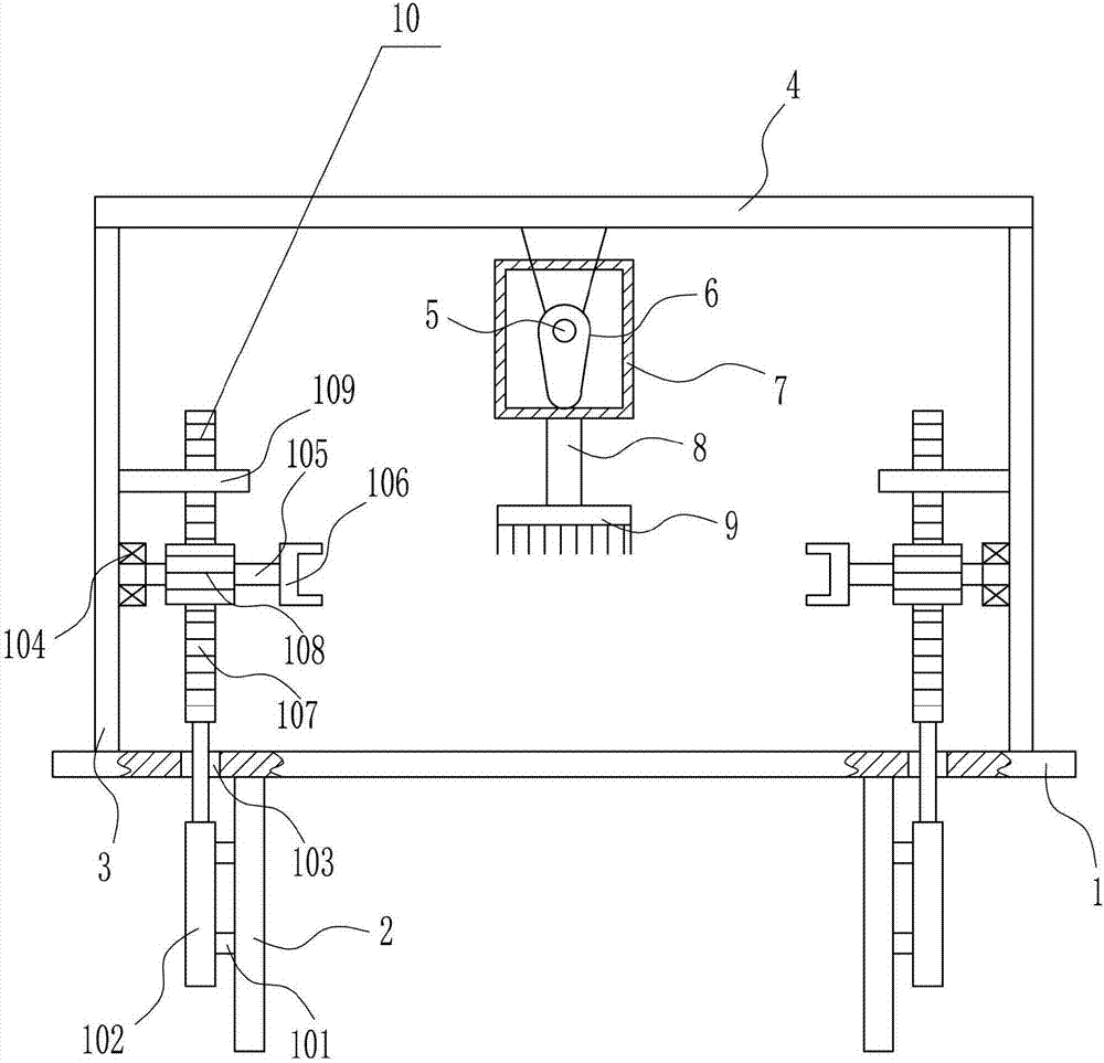
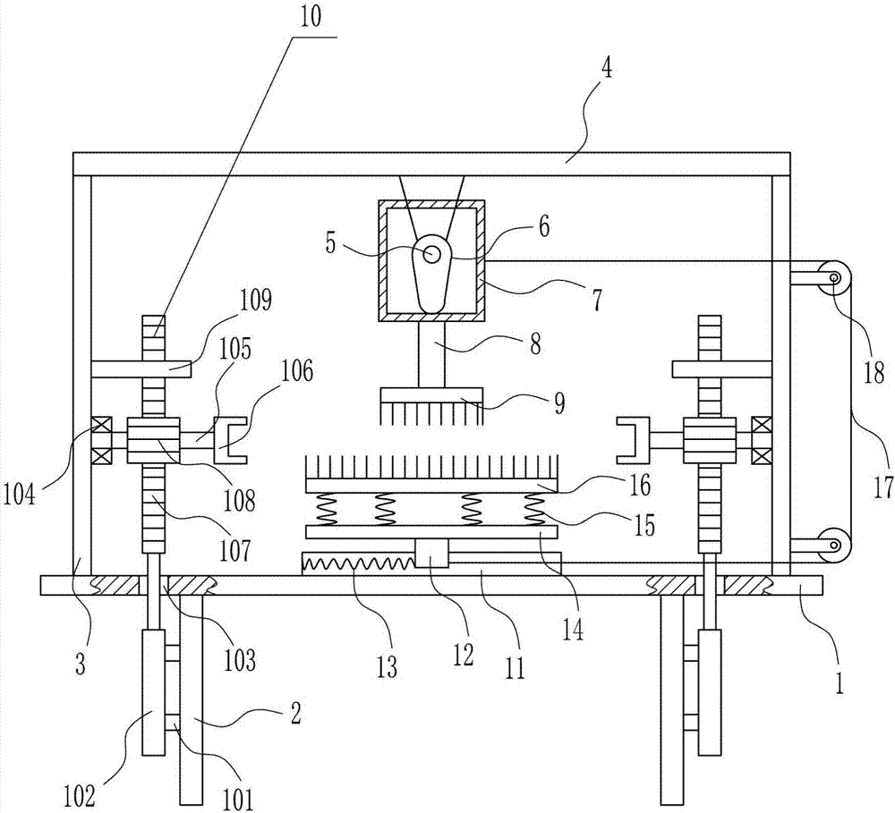
[0027] A kind of high-efficiency derusting equipment for steel bars for construction, such as Figure 1-3 As shown, it includes a bottom plate 1, a leg 2, a support plate 3, a top plate 4, a first motor 5, a cam 6, a frame body 7, a vertical rod 8, a first wire brush 9 and a rotating device 10, and the left and right sides of the bottom of the bottom plate 1 Outriggers 2 are installed on both sides by bolts, support plates 3 are installed on the left and right sides of the top of bottom plate 1 by bolts, top plates 4 are installed on the top of support plates 3 by bolts, and the middle of the bottom of top plates 4 passes through The first motor 5 is installed in the way of bolt connection, and the cam 6 is installed on the output shaft of the first motor 5 through bolt connection. Located in the frame body 7, a vertical rod 8 is installed in the middle of the outer bottom of the frame body 7 through bolt connection, a first wire brush 9 is installed at the bottom end of the v...

Embodiment 2

[0029] A kind of high-efficiency derusting equipment for steel bars for construction, such as Figure 1-3As shown, it includes a bottom plate 1, a leg 2, a support plate 3, a top plate 4, a first motor 5, a cam 6, a frame body 7, a vertical rod 8, a first wire brush 9 and a rotating device 10, and the left and right sides of the bottom of the bottom plate 1 Outriggers 2 are installed on both sides by bolts, support plates 3 are installed on the left and right sides of the top of bottom plate 1 by bolts, top plates 4 are installed on the top of support plates 3 by bolts, and the middle of the bottom of top plates 4 passes through The first motor 5 is installed in the way of bolt connection, and the cam 6 is installed on the output shaft of the first motor 5 through bolt connection. Located in the frame body 7, a vertical rod 8 is installed in the middle of the outer bottom of the frame body 7 through bolt connection, a first wire brush 9 is installed at the bottom end of the ve...

Embodiment 3

[0032] A kind of high-efficiency derusting equipment for steel bars for construction, such as Figure 1-3 As shown, it includes a bottom plate 1, a leg 2, a support plate 3, a top plate 4, a first motor 5, a cam 6, a frame body 7, a vertical rod 8, a first wire brush 9 and a rotating device 10, and the left and right sides of the bottom of the bottom plate 1 Outriggers 2 are installed on both sides by bolts, support plates 3 are installed on the left and right sides of the top of bottom plate 1 by bolts, top plates 4 are installed on the top of support plates 3 by bolts, and the middle of the bottom of top plates 4 passes through The first motor 5 is installed in the way of bolt connection, and the cam 6 is installed on the output shaft of the first motor 5 through bolt connection. Located in the frame body 7, a vertical rod 8 is installed in the middle of the outer bottom of the frame body 7 through bolt connection, a first wire brush 9 is installed at the bottom end of the v...


PUM


Abstract

The invention relates to a derusting device for steel bars for construction, in particular to a high-efficiency derusting device for steel bars for construction. The technical problem to be solved by the present invention is to provide a high-efficiency derusting equipment for building steel bars that does not require a large amount of labor, has short derusting time, and is not easy to be injured during the derusting process. In order to solve the above technical problems, the present invention provides such a high-efficiency derusting equipment for steel bars for construction, which includes a bottom plate, legs, support plates, top plate, first motor, cam, frame, vertical bar, etc.; Outriggers are installed on the sides by bolts, support plates are installed on the left and right sides of the top of the bottom plate by bolts, and a top plate is installed on the top of the support plate by bolts. In the present invention, the first steel wire brush and the second steel wire brush move left and right to double derust the steel bar, so that the derusting effect of the steel bar is better, and at the same time, the rotation of the steel bar is improved.

Description

technical field [0001] The invention relates to a derusting device for steel bars for construction, in particular to a high-efficiency derusting device for steel bars for construction. Background technique [0002] Reinforcement refers to steel for reinforced concrete and prestressed reinforced concrete, which is circular in cross-section and sometimes square with rounded corners. Including plain round bars, ribbed bars, twisted bars. Steel bars for reinforced concrete refer to the straight or coiled steel used for reinforced concrete reinforcement. Its shape is divided into two types: smooth round steel bar and deformed steel bar. The delivery state is straight bar and coiled round. [0003] If the steel bar is placed for a long time, it will come into contact with water and air, and iron oxide, that is, rust will appear on the surface. If the rust on the rusty steel bar is not clean, it will affect the bearing capacity of the steel bar. When the steel bar is derusted, it...

Claims


Application Information

Patent Timeline
Patent Type & Authority Applications(China)
IPC IPC(8): B24B27/04B24B41/06B24B41/02B24B47/12B24B47/14
CPCB24B27/04B24B41/02B24B41/06B24B47/12B24B47/14
Inventor 孔军玲
Owner 孔军玲
Why Eureka
Try Eureka