Air vehicle

A technology of aircraft and travel direction, applied in the field of aircraft, can solve the problems of unfavorable flight of small aircraft, increase of aircraft load, short flight time, etc., and achieve the effects of long-term battery life, increased load weight, and increased voyage distance

Active Publication Date: 2017-07-14
张爱伦
View PDF11 Cites 3 Cited by
  • Summary
  • Abstract
  • Description
  • Claims
  • Application Information

AI Technical Summary

Problems solved by technology

[0002] Most small aircraft are powered by lithium batteries, which have the disadvantages of short voyage time and short range; while the engines using gasoline, methanol and other fuels have a large mass, and for multi-rotor aircraft, multiple engines need to be installed, which increases the load of the aircraft , is not conducive to the flight of small aircraft

Method used


Image

  • Air vehicle
  • Air vehicle
  • Air vehicle

Examples


example 1

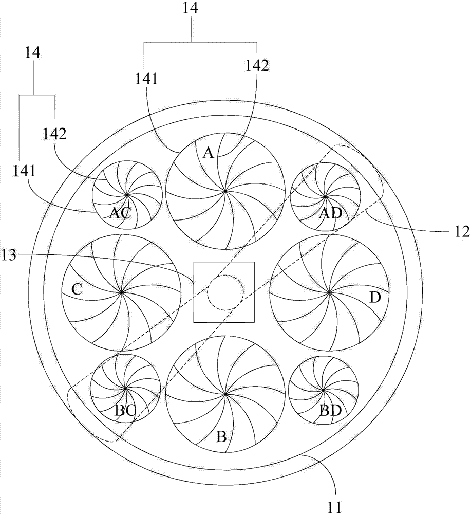
[0035] refer to image 3 As shown, the air hole 141 of the air hole structure 14 runs through the top and bottom of the fuselage 11 up and down. Rotate to change the opening and closing size of the air hole 141 . Among them, the aperture adjusting damper is a kind of prior art, which is a kind of air volume regulating valve installed in the pipeline structure. The structure is similar to the aperture structure in the camera. The rotation of the disk drives the multiple arc-shaped plates connected to it through the pins to rotate and move around the pins connected to the housing respectively, thereby controlling and adjusting the opening size of the damper formed by the above-mentioned multiple arc-shaped plates. In this embodiment, the above-mentioned aperture adjustment door is installed in the air hole, and the opening and closing size of the air hole can be adjusted by means of the function of rotating the aperture adjustment door to adjust the opening size of the damper. ...

example 2

[0038] refer to Figure 4 Shown is a structural schematic view of another embodiment of the air hole structure in the aircraft of the present invention. The ventilation hole 141 of the air hole structure 14 runs through the top and the bottom of the fuselage 11 up and down, and the air regulation assembly 142 includes a steering gear (not labeled), a first rotary rod 1421 and a second rotary rod 1422 . Wherein, the steering gear is installed on the fuselage of the aircraft and is arranged at the center of the air hole 141. The first rotating rod 1421 and the second rotating rod 1422 adopt small rods, which are installed on the steering gear and rotate under the driving of the steering gear. In the figure, the steering gear is installed at the middle position between the first rotating rod 1421 and the second rotating rod 1422, and the first rotating rod 1421 and the second rotating rod 1422 rotate relatively under the driving of the steering gear. A flexible sealing layer 142...


PUM


Abstract

The invention discloses an air vehicle which comprises a vehicle body, a rotor wing mounted at the top of the vehicle body and a power system connected to the rotor wing. The vehicle body is provided with a plurality of retractable air hole structures corresponding to the lower portion of the rotor wing. Airflow generated during rotation of the rotor wing flows through the corresponding air hole structures to adjust the flight direction and speed of the vehicle body. According to the air vehicle, by forming the air hole structures in the vehicle body, the air hole structures correspond to all the travelling directions of the vehicle body and are formed below the rotor wing, so that the airflow generated during rotation of the rotor wing flows through the corresponding air hole structures to adjust the flight direction and speed of the vehicle body, the scheme that the flight direction and speed of an air vehicle are controlled by arranging a plurality of rotor wings is replaced, normal flight of the air vehicle can be completed only by one rotor wing, the load of the vehicle body is decreased, and long-time endurance of the air vehicle is more facilitated.

Description

technical field [0001] The invention relates to an aircraft. Background technique [0002] Most small aircraft are powered by lithium batteries, which have the disadvantages of short voyage time and short range; while the engines using gasoline, methanol and other fuels have a large mass, and for multi-rotor aircraft, multiple engines need to be installed, which increases the load of the aircraft , is not conducive to the flight of small aircraft. Contents of the invention [0003] The technical problem to be solved by the present invention is to provide an aircraft that can prolong the flight time without increasing the load. [0004] In order to achieve the above technical effect, the present invention discloses an aircraft, which includes a fuselage, a rotor mounted on the top of the fuselage, and a power system connected to the rotor; A plurality of shrinkable air hole structures, the airflow generated when the rotor rotates flows through the corresponding air hole s...

Claims


Application Information

Patent Timeline
Patent Type & Authority Applications(China)
IPC IPC(8): B64C27/08B64C27/12B64C1/00
CPCB64C1/0009B64C27/08B64C27/12
Inventor 张爱伦
Owner 张爱伦
Why Eureka
Try Eureka