
In-hole cavity monitoring device and method based on multi-frequency ultrasonic scanning

A multi-frequency ultrasonic and detection device technology, which is applied in measurement devices, processing response signals of detection, and material analysis using sonic/ultrasonic/infrasonic waves, which can solve problems such as poor detection accuracy and limited detection range.

Active Publication Date: 2017-07-14
INST OF ROCK AND SOIL MECHANICS - CHINESE ACAD OF SCI
View PDF8 Cites 11 Cited by
  • Summary
  • Abstract
  • Description
  • Claims
  • Application Information

AI Technical Summary

Problems solved by technology

[0007] The purpose of the present invention is to overcome the shortcomings and shortcomings of limited detection range and poor detection accuracy caused by a single ultrasonic detection frequency in the past, and propose a detection device for voids in holes based on multi-frequency ultrasonic scanning. Ultrasonic scanning method for detecting voids in boreholes, using phase difference of two frequencies to accurately calculate ranging value, combining scan point azimuth and depth to form three-dimensional outline of voids, and forming a set of multiple frequency transducers The rotatable scanning hole detection device for voids, that is, the detection device for voids in holes based on multi-frequency ultrasonic scanning, can realize high-precision scanning of rock walls in voids, complete the detection of voids without dead ends, and form a three-dimensional view of voids contour

Method used


Image

  • In-hole cavity monitoring device and method based on multi-frequency ultrasonic scanning
  • In-hole cavity monitoring device and method based on multi-frequency ultrasonic scanning
  • In-hole cavity monitoring device and method based on multi-frequency ultrasonic scanning

Examples


Embodiment Construction

[0062] Below in conjunction with accompanying drawing and implementation example the present invention is further described:

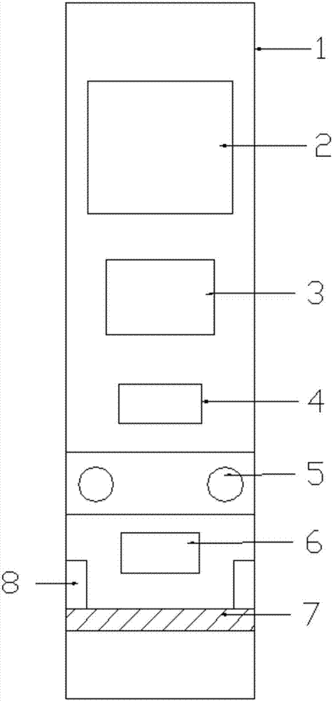
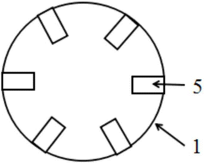
[0063] Such as figure 1 As shown, a multi-frequency ultrasonic scan-based detection device for hollow space in a hole includes a probe in the hole, a cable, a depth encoder, a data line, a computer and a power supply. The probe in the hole is used to accurately detect the scan on the rock wall of the hollow Points and the orientation and length of the scanning line where the ultrasonic transducer is located, the probe in the hole is placed in the empty space in the hole, the probe in the hole is lowered into the hole through the cable, and the collected data is uploaded to the computer on the ground through the cable, When the probe in the hole is lowered from the hole, the depth encoder at the hole starts to work, which is used to record the depth of the probe in the hole, so as to calculate the depth information of the scanning point on the rock wall...


PUM


Abstract

The invention discloses an in-hole cavity monitoring device and method based on multi-frequency ultrasonic scanning. The in-hole cavity monitoring device comprises a rotary driving component, an orientation component, a scanning component, a calibrating component and a reflection component. The invention further discloses an in-hole cavity monitoring method based on multi-frequency ultrasonic scanning, and aims to solve the problems of limit and low accuracy in a single-frequency ultrasonic detection range. Clear waveforms generated by selecting ultrasonic energy converters of two frequencies are comparatively analyzed in order to calculate the number of periods of ultrasonic pulse leak detection respectively, so that the transmission time detection accuracy is increased; meanwhile, the calibrating component and the reflection component are adopted in order to measure a sound speed in an environmental medium to realize high-accuracy measurement of a wave speed; lastly, distance values measured by the ultrasonic energy converters of two frequencies are averaged to obtain an accurate distance. The in-hole cavity monitoring device and method have the advantages of skillful design, strict concept, simple structural system, and easiness in implementation.

Description

technical field [0001] The present invention relates to the field of geotechnical measurement devices, in particular to a detection device for voids in holes based on multi-frequency ultrasonic scanning, and also relates to a detection method for voids in holes based on multi-frequency ultrasonic scanning, which is applicable to various engineering fields Carry out detailed survey and detection of voids in geological boreholes, obtain fine geological structure and contour information of voids, and realize accurate detection of voids of various sizes within the range without blind spots. Background technique [0002] With the rapid development of my country's society and economy, the demand for mineral resources has increased sharply. my country has entered the stage of large-scale development of mineral resources and most of them are underground mining. Underground mining of mineral resources will inevitably form a large number of goafs, and the goafs may cause large-scale u...

Claims


Application Information

Patent Timeline
Patent Type & Authority Applications(China)
IPC IPC(8): G01N29/44
CPCG01N29/449G01N2291/011
Inventor 汪进超王川婴
Owner INST OF ROCK AND SOIL MECHANICS - CHINESE ACAD OF SCI
Learn More