A delay mechanism and circuit breaker

A technology of time-delay mechanism and tripping mechanism, applied in the direction of operation/release mechanism of protection switch, circuit, electrical components, etc., can solve the problem of short delay time of delay mechanism, short delay time of circuit breaker, poor delay effect, etc. problem, to achieve the effect of long delay time and good delay effect

Active Publication Date: 2019-03-22
XIAMEN TAIHANG TECH
View PDF4 Cites 0 Cited by
  • Summary
  • Abstract
  • Description
  • Claims
  • Application Information

AI Technical Summary

Problems solved by technology

[0004] The purpose of the present invention is to provide a time-delay mechanism to improve the problems of short delay time and poor delay effect of the time-delay mechanism.
[0005] The purpose of the present invention is to provide a circuit breaker to improve the problems of short delay time and poor delay effect of the circuit breaker

Method used


Image

  • A delay mechanism and circuit breaker
  • A delay mechanism and circuit breaker
  • A delay mechanism and circuit breaker

Examples


Embodiment 1

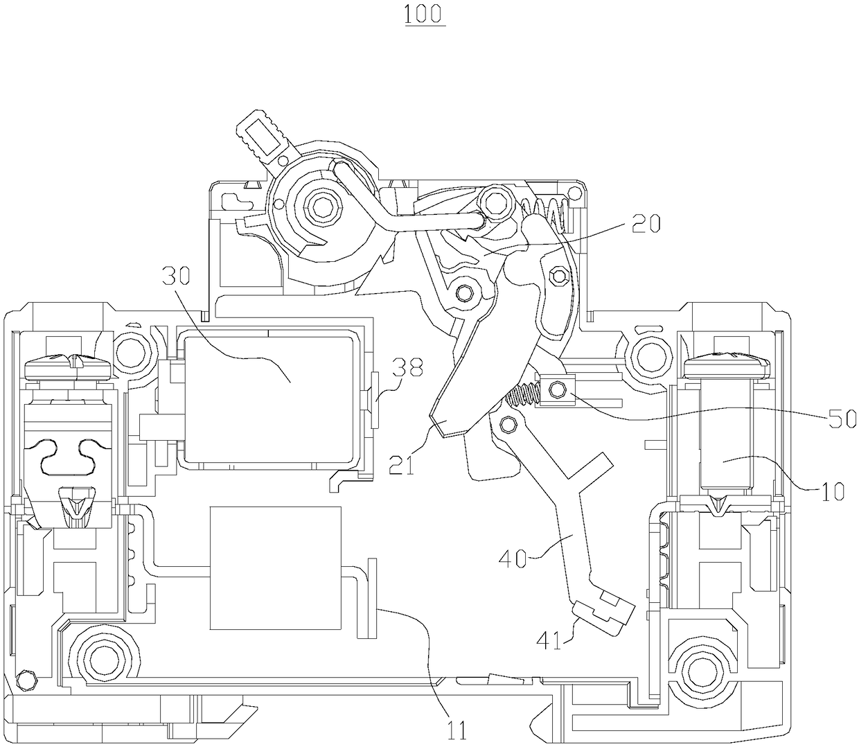
[0040] Such as figure 1 As shown, a circuit breaker 100 is provided, including a housing 10 , a tripping mechanism 20 , a delay mechanism 30 , an actuator 40 and a return mechanism 50 . The delay mechanism 30 is set in the housing 10, the tripping mechanism 20 is rotatably arranged in the housing 10, the tripping mechanism 20 has a contact part 21, the actuator part 40 is connected with the housing 10 in rotation, and the actuator part 40 is provided with a moving contact 41. The housing 10 is provided with a static contact 11. Under normal conditions, the return mechanism 50 acts on the actuator 40 to make the moving contact 41 contact with the static contact 11; when there is a short circuit or overload, the delay mechanism 30 will delay the action on the contact part 21 of the tripping mechanism 20, so that the The tripping mechanism 20 trips and drives the actuator 40 to rotate, so that the moving contact 41 is separated from the static contact 11 .

[0041] Among them, ...

Embodiment 2

[0055] Such as Figure 4 As shown, this embodiment provides a circuit breaker 100, and the difference from the above embodiments lies in that the structure of the moving iron core 35 in the delay mechanism 30 is different.

[0056] In this embodiment, the moving iron core 35 is also provided with a limiting portion and a trigger 38 .

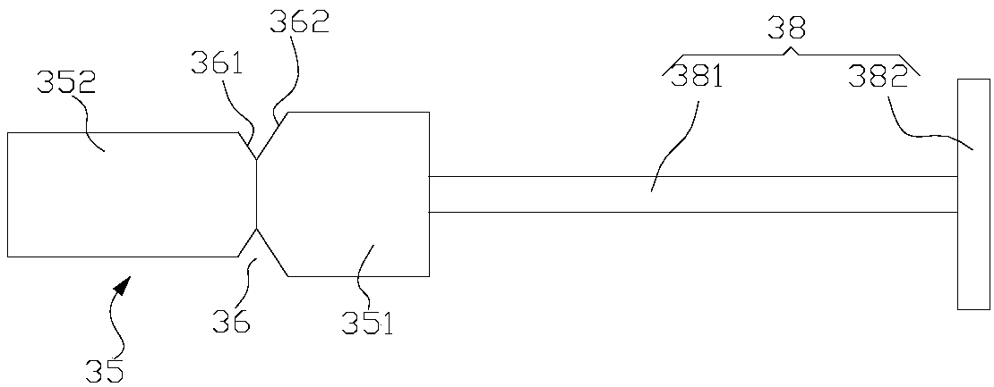
[0057] Such as Figure 5 As shown, the moving iron core 35 includes a first connecting body 351 and a second connecting body 352, the first connecting body 351 is arranged at one end of the second connecting body 352, and both the first connecting body 351 and the second connecting body 352 are cylinders . The axial projection of the second connecting body 352 is completely inside the first connecting body 351 , that is, the diameter of the second connecting body 352 is smaller than the diameter of the first connecting body 351 . The diameter of the first connecting body 351 matches the inner diameter of the housing 31 .

[0058] In this emb...

Embodiment 3

[0064] Such as Figure 6 As shown, this embodiment provides a circuit breaker 100, the difference from Embodiment 1 is that the structure of the moving iron core 35 in the delay mechanism 30 is different.

[0065] In this embodiment, the moving iron core 35 is also provided with a limiting portion and a trigger 38 .

[0066] Such as Figure 7 As shown, the moving iron core 35 is cylindrical, and the end of the connecting rod 381 in the triggering member 38 away from the triggering portion 382 is fixed to the moving iron core 35 . In this embodiment, the limiting portion is a protruding portion 37 provided on the outer circumference of the moving iron core 35 . The protruding portion 37 includes a first guiding slope 371 and a second guiding slope 372 facing away from each other. The first guiding slope 371 is closer to the trigger member 38 than the second guiding slope 372 . The slope of the first guiding slope 371 is greater than that of the second guiding slope 372 , tha...


PUM


Abstract

The invention provides a delay mechanism and a circuit breaker, belonging to the field of circuit protection devices. Wherein, the delay mechanism includes a shell, an electromagnetic coil, a static iron core and a moving iron core. The electromagnetic coil is wound on the outside of the casing, the static iron core is fixed in the casing, and the static iron core is slidably arranged in the casing. The moving iron core is provided with a limiting part and a trigger part, and the housing is provided with an elastic limiting part. The limiting part can constrain the elastic limiting part and limit the sliding of the moving iron core relative to the static iron core in the first direction. It is the direction in which the moving iron core slides close to the static iron core. When the electromagnetic coil is fed with an over-load current, the elastic limiter can be deformed and break away from the restraint of the limiter, so that the moving iron core slides in the first direction relative to the static iron core, so that the trigger member triggers the tripping mechanism. The time-delay process of this time-delay mechanism is the process in which the elastic limiter is not separated from the limiter, and the delay time is relatively long, which has a good delay effect.

Description

technical field [0001] The invention relates to the field of circuit protection devices, in particular to a delay mechanism and a circuit breaker. Background technique [0002] Short-circuit failures occur due to various reasons such as power supply systems and electrical equipment. The power supply system often relies on miniature circuit breakers to disconnect the circuit. Misoperation of miniature circuit breakers has always been a problem. When the short-circuit fault current exceeds the current level, the upper level, and even the next level, as for which level of miniature circuit breaker action is random, this is the problem of the miniature circuit breaker malfunctioning and tripping over the next level. In civil power supply lines, different sections of power supply cables have different DC resistances, so the line impedance formed by the length of the line plays a certain protective role: when a line short-circuit fault occurs at the user end, the line impedance li...

Claims


Application Information

Patent Timeline
Patent Type & Authority Patents(China)
IPC IPC(8): H01H71/44H01H71/24
CPCH01H71/2463H01H71/44
Inventor 李欣
Owner XIAMEN TAIHANG TECH
Why Eureka
Try Eureka