Vibrating diaphragm mechanism applied to receiver

A receiver and reed technology, applied in the field of receivers, can solve the problems of not being able to improve the high-frequency performance of the diaphragm mechanism

Pending Publication Date: 2017-07-14
SUZHOU YICHUAN TECH CO LTD
View PDF1 Cites 4 Cited by
  • Summary
  • Abstract
  • Description
  • Claims
  • Application Information

AI Technical Summary

Problems solved by technology

[0005] Therefore, the technical problem to be solved by the present invention is to overcome the problem that the diaphragm mechanism of the receiver in the prior art can only improve the low-frequency performance of the bass, but cannot improve the high-frequency performance of the diaphragm mechanism

Method used


Image

  • Vibrating diaphragm mechanism applied to receiver
  • Vibrating diaphragm mechanism applied to receiver
  • Vibrating diaphragm mechanism applied to receiver

Examples


Embodiment 1

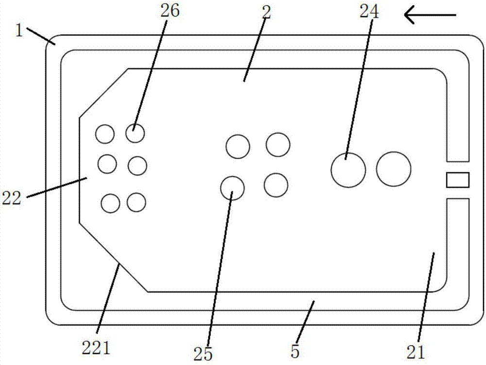
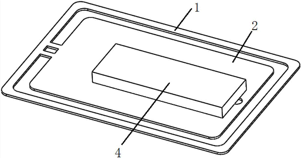
[0044] This embodiment provides a diaphragm mechanism applied to a receiver, such as Figure 1 to Figure 3 As shown, it includes a fixed frame 1, a reed 2 and a sound membrane 3. Wherein, the fixed frame 1 has a hollow inner cavity.

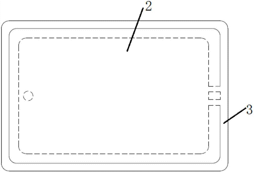
[0045] The reed 2 is made of magnetically permeable material, such as iron-nickel alloy, such as figure 1 As shown, one end of the reed 2 is connected to the fixed frame 1 through the fixed end 21 at one end of the reed 2, and there is a gap 5 between the other sides and the fixed frame 1. The opposite end of 21 is a floating end 22, and the floating end 22 is driven by the electromagnetic mechanism to reciprocate and vibrate; as image 3 As shown, the sound membrane 3 is all attached to the entire fixed frame 1 and covered on the reed 2 to seal the airflow passage between the upper and lower surfaces of the fixed frame 1 and the reed 2 formed by the gap 5 . For example, glue is provided on one side of the sound membrane 3 at positions corresp...


PUM


Abstract

The invention discloses a diaphragm mechanism applied to a receiver, comprising a fixed frame, a reed and a sound diaphragm. The fixed frame has a hollow cavity; one end of the reed is connected to the fixed frame through the fixed end at the root side, and a gap is formed between the other sides and the fixed frame, and is suspended in the hollow cavity; the reed corresponds to the edge of the side of the gap The shape is determined according to the vibration frequency required by the reed; the reed is driven by the electromagnetic mechanism to vibrate back and forth; the sound film is fixed on the fixed frame and covered on the reed; the sealing gap is formed between the upper and lower surfaces of the fixed frame and the reed. air passages in between. According to the required vibration frequency of the reed, the edge shape of the side of the reed corresponding to the gap is determined, that is, the edge shape of the floating end opposite to the fixed end on the reed is changed to change the required high-pitched sound when the reed vibrates. Vibration frequency, so that the reed and the air resonance point shift, thereby improving the high frequency performance of the receiver.

Description

technical field [0001] The invention relates to the technical field of receivers, in particular to a diaphragm mechanism applied to receivers. Background technique [0002] The receiver is an electroacoustic device that converts audio electrical signals into audio signals without sound leakage. It is widely used in communication terminal equipment such as mobile phones, fixed phones, and earphones to realize audio output. [0003] With the continuous development of mobile devices, people have higher and higher requirements for the quality of receivers, such as the requirements for low-frequency performance of receivers. A receiver with good low-frequency performance disclosed in Chinese patent document CN204498334U includes a shell, which is horizontally installed on the shell The flapping mechanism in the body divides the shell into two cavities vertically. The vibrating wing mechanism includes a fixed frame, a vibrating piece and a sound film. The sound film is first fixe...

Claims


Application Information

Patent Timeline
Patent Type & Authority Applications(China)
IPC IPC(8): H04R7/08
CPCH04R7/08H04R2207/021
Inventor 吴哲
Owner SUZHOU YICHUAN TECH CO LTD
Why Eureka
Try Eureka