Separating device for kiln flue gas

A separation device and flue gas technology, which is applied in the direction of combination device, separation method, and dispersed particle separation, can solve the problems of polluted air, poor treatment effect, and health hazards, and achieve the goal of improving purification effect, reducing replacement, and reducing pressure Effect

Inactive Publication Date: 2017-07-18
CHENGDU SINOMETALLURGY ENERGY CONSERVATION ENVIRONMENTAL PROTECTION ENG CO LTD
View PDF0 Cites 0 Cited by
  • Summary
  • Abstract
  • Description
  • Claims
  • Application Information

AI Technical Summary

Problems solved by technology

At present, industrial furnaces produce a large amount of smoke particles during operation. These smoke particles contain a large amount of toxic substances, which seriously pollute the air and are very harmful to people's health.
Some flue gas treatment is complicated, the treatment cost is high, and some treatment effects are poor, it is difficult to meet environmental protection requirements, and even secondary pollution exists

Method used


Image

  • Separating device for kiln flue gas
  • Separating device for kiln flue gas
  • Separating device for kiln flue gas

Examples


Embodiment 1

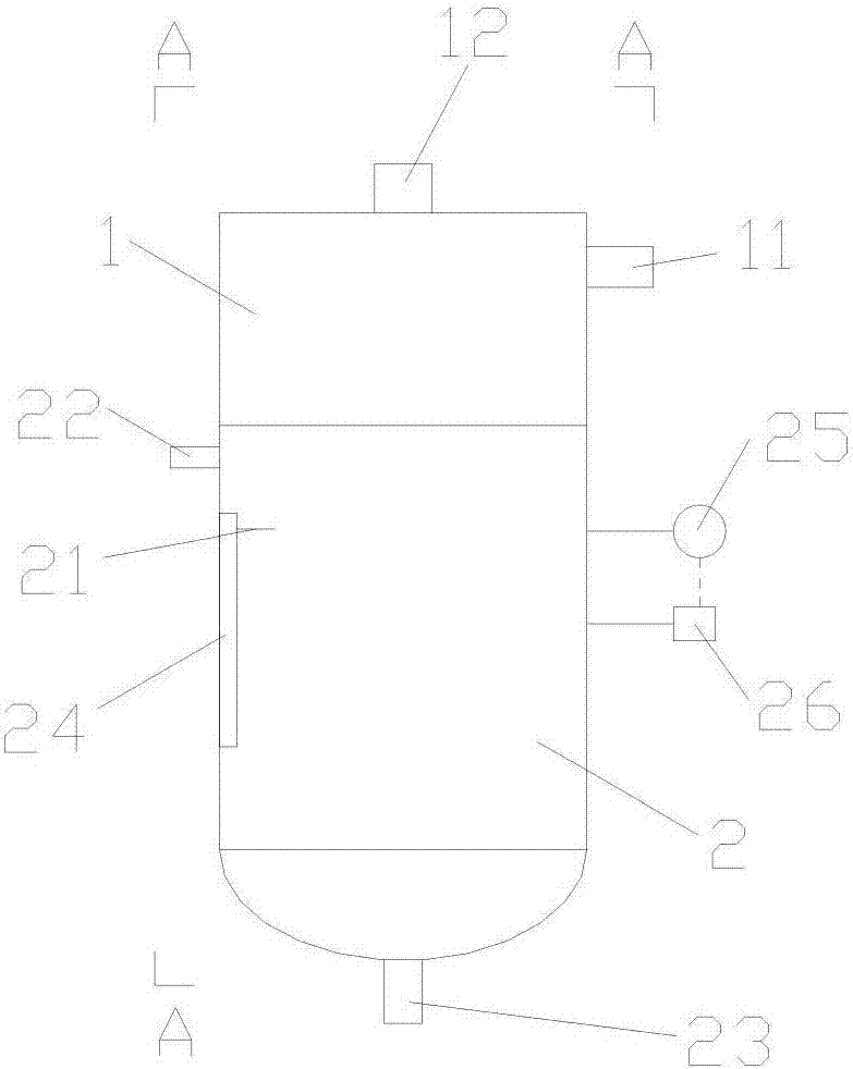
[0029] A separation device for kiln flue gas, such as figure 1 As shown, the separation device includes a cylinder, the cylinder includes an upper cylinder 1 and a lower cylinder 2, and the upper cylinder and the lower cylinder are snap-connected to form a closed cylinder cavity, and the upper cylinder and the lower cylinder form a closed cylinder cavity. The body snap connection is for easy disassembly and subsequent cleaning and maintenance.

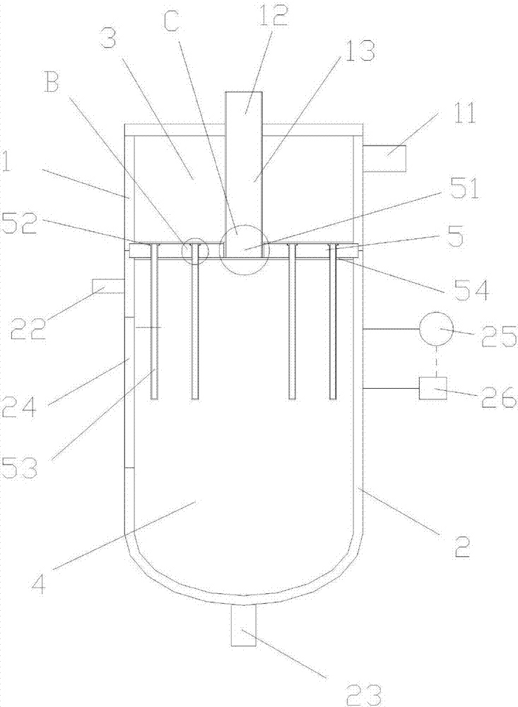
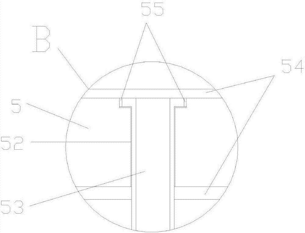
[0030] like figure 2 As shown in the figure, at the junction of the upper cylinder and the lower cylinder, there is a partition plate 5 that separates the cylinder cavity into the upper cavity 3 and the lower cavity 4; the side wall of the upper cylinder 1 is provided with The flue gas inlet 11 communicated with the upper cavity 2, the top of the upper cylinder is provided with a first clean gas outlet 12; the side wall of the lower cylinder 2 is provided with a rated liquid level line 21, the side wall of the lower cylinder is provi...

Embodiment 2

[0035] In this embodiment, on the basis of Embodiment 1, a liquid level gauge 25 and a liquid level alarm device 26 connected to the liquid level gauge 25 are added on the lower cylinder. It makes its detection more automatic, saving time and effort.

Embodiment 3

[0037] In this embodiment, a further improvement is made on the basis of Embodiment 1 or 2. The bottom of the lower cylinder body 2 is elliptical arc shape, and the sewage outlet 23 is set at the lowest part of the bottom. It can prevent the dirty liquid from depositing on the bottom of the lower cylinder and block the sewage outlet, which is beneficial to the sewage discharge from the sewage outlet.


PUM


Abstract

The invention discloses a separating device for a kiln flue gas. The separating device comprises a drum; the drum comprises an upper drum body and a lower drum body; a closed drum chamber is formed after the upper drum body and the lower drum body are buckled with each other; a separating plate which is used for separating the drum chamber into an upper chamber body and a lower chamber body is arranged at a joint of the upper drum body and the lower drum body; a flue gas inlet is formed on a side wall of the upper drum body; a first purified gas outlet is formed at the top of the upper drum body; a rated liquid level line is arranged on a side wall of the lower drum body; a liquid inlet is formed on the side wall of the lower drum body and above the rated liquid level line; a drain outlet is formed at the bottom of the lower drum body; HEPA filtering screens are arranged at the first purified gas outlet and the inlet ends of all the guide pipes. The separating device is free from secondary pollution in a separating process, has an excellent purifying effect, is low in processing cost, is simple and convenient in use and is wide in application scope.

Description

technical field [0001] The invention relates to the technical field of flue gas treatment, in particular to a separation device for furnace flue gas. Background technique [0002] The smoke and dust generated by the combustion process of fuel and other substances, as well as the mechanical processes such as crushing, screening and conveying of solid materials, generate a large amount of smoke and dust. At present, a large number of flue gas particles are generated during the operation of industrial furnaces. These flue gas particles contain a large amount of toxic substances, which seriously pollute the air and cause great harm to people's health. Some flue gas treatment is complicated, the treatment cost is high, some treatment effect is poor, it is difficult to meet the environmental protection requirements, and even there is secondary pollution. SUMMARY OF THE INVENTION [0003] The purpose of the present invention is to solve the above-mentioned technical problems, an...

Claims


Application Information

Patent Timeline
Patent Type & Authority Applications(China)
IPC IPC(8): B01D50/00
CPCB01D50/60
Inventor 王蓉
Owner CHENGDU SINOMETALLURGY ENERGY CONSERVATION ENVIRONMENTAL PROTECTION ENG CO LTD
Why Eureka
Try Eureka