Composite shock-resisting structure and forming method thereof
What is AI technical title?
AI technical title is built by Patsnap AI team. It summarizes the technical point description of the patent document.
A composite material and molding method technology, applied in chemical instruments and methods, lamination devices, lamination auxiliary operations, etc., can solve the problems of high cost, complex weaving process, and difficult manufacturing, and achieve high manufacturing efficiency and improve the overall Stiffness, the effect of improving damage tolerance
Active Publication Date: 2017-07-18
AEROSPACE RES INST OF MATERIAL & PROCESSING TECH +1
View PDF4 Cites 10 Cited by
Summary
Abstract
Description
Claims
Application Information
AI Technical Summary
This helps you quickly interpret patents by identifying the three key elements:
Problems solved by technology
Method used
Benefits of technology
Problems solved by technology
[0003] The above method has complicated weaving process, great manufacturing difficulty and high cost
Method used
Image
Click on the blue label to locate the original text in one second.
Reading with bidirectional positioning of images and text.
Examples
Embodiment 1
[0121] 1) select the ring mold;
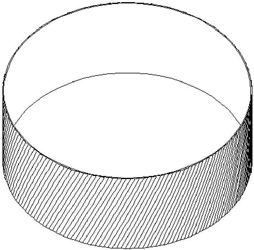
[0122] 2) Wrap the annular layer prepreg tape along the annular mold ring to 0° direction until the surface of the annular mold is covered to form an annular layer of continuous fibers; the annular layer prepreg tape adopts carbon fiber prepreg with a width of 50mm;
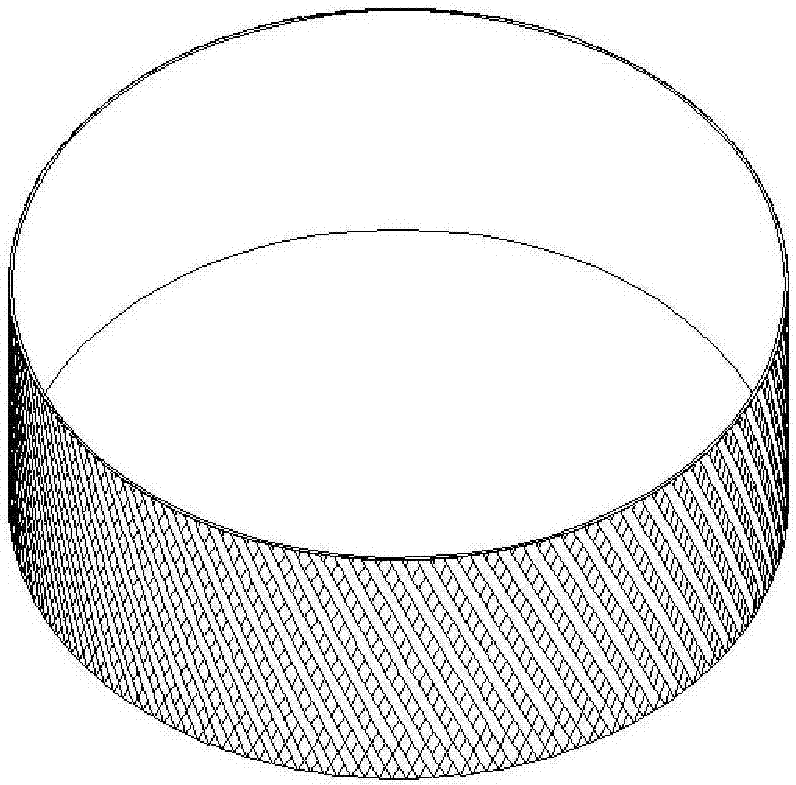
[0123] 3) According to the layup angle of 60°, lay a first prepreg tape every 12.9mm, so as to cover the entire cylinder, the prepreg used for the first prepreg tape is carbon fiber prepreg, prepreg Belt width 12.7mm (such as figure 2 shown);
[0124] 4) According to the layer angle of -60°, lay a second prepreg tape at an interval of 12.9mm, so as to cover the entire cylinder, the prepreg used for the second prepreg tape is carbon fiber prepreg, prepreg Dip tape width 12.7mm (such as image 3 shown);
[0125] 5) Lay the first prepreg tape (such as Figure 4 As shown), the width of the prepreg tape is 12.7mm, so that it covers the entire cylinder;
[0126] 6) According to ...
Embodiment 2
[0131] 1) select the ring mold;
[0132] 2) Lay the annular layer prepreg tape along the annular mold ring direction 0° until the surface of the annular mold is covered to form an annular layer of continuous fibers; the annular layer prepreg tape adopts aramid fiber prepreg, and the prepreg Width 80mm;
[0133] 3) According to the layup angle of 60°, lay a first prepreg tape, the prepreg used in the first prepreg tape is glass fiber prepreg, and the width of the prepreg tape is 6.35mm;
[0134] 4) According to the layup angle of -45°, lay a second prepreg tape, the prepreg used in the second prepreg tape is carbon fiber prepreg, and the width of the prepreg tape is 12.7mm (see Image 6 );
[0135] 5) Lay another first prepreg tape with a width of 6.45 mm from the first prepreg tape laid last time;
[0136] 6) Lay another second prepreg tape at a width of 13.1 mm from the second prepreg tape laid last time; (see Figure 7 )
[0137] 7) Repeat steps 5) and 6) in turn until ...
PUM
Abstract
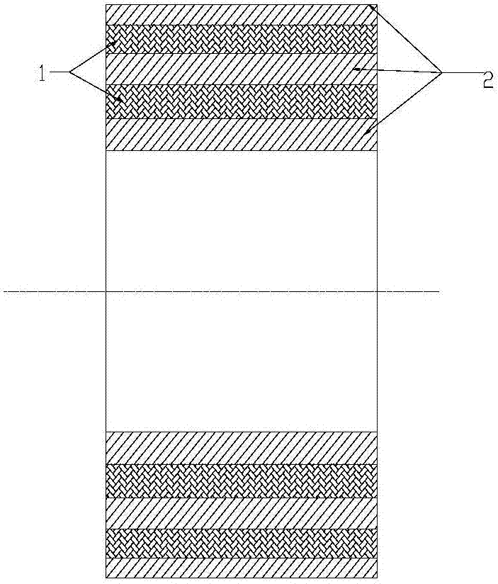
The invention relates to a composite shock-resisting structure and a forming method thereof, which aims at solving the problem of low-cost manufacturing of an annular shock-resisting structure, and belongs to the technical field of manufacturing of structural composite materials. The composite shock-resisting structure disclosed by the invention has an overlapped layer; the overlapped layer is of a gridding interweaved structure which is formed by interweaving and superposing adjacent laying pre-soaking tapes and a 2-dimensional laminating structure of a traditional composite laminating plate is changed into a 2.5-dimensional laminating structure, so that the interlayer performance and impactdamage tolerance of the shock-resisting structure are increased by 15% or above and the shock resistance is better; annular layers of the composite shock-resisting structure have excellent fiber continuity and straightening property and the mechanical property of the composite material can be brought into play to the greatest extent; the overlapped layer tightly loops between the two annular layers, so that the damage tolerance and interlayer property of the overlapped layer can be further promoted; thus, the composite shock-resisting structure provided by the invention has the advantage of excellent shock and damage resistance.
Description
technical field [0001] The invention provides a composite material structure with anti-impact damage performance and a forming method thereof, belonging to the technical field of structural composite material manufacturing. Background technique [0002] The engine is the core component of an aviation vehicle. In order to prevent or reduce the impact damage to the engine during flight, the aero-engine containing case is made of a three-dimensional fabric with strong impact resistance. The three-dimensional fabric is passed through RTM (Resin Transfer Molding, resin transfer Molding) molding, when molding, first according to the design size of the engine containing casing, through three-dimensional weaving, using dry yarn weaving molding, and then injecting resin into the molding fabric to obtain the finished product. [0003] The above method has complicated weaving process, great manufacturing difficulty and high cost. Therefore, there is an urgent need for a composite impa...
Claims
Application Information
Patent Timeline
Application Date:The date an application was filed.
Publication Date:The date a patent or application was officially published.
First Publication Date:The earliest publication date of a patent with the same application number.
Issue Date:Publication date of the patent grant document.
PCT Entry Date:The Entry date of PCT National Phase.
Estimated Expiry Date:The statutory expiry date of a patent right according to the Patent Law, and it is the longest term of protection that the patent right can achieve without the termination of the patent right due to other reasons(Term extension factor has been taken into account ).
Invalid Date:Actual expiry date is based on effective date or publication date of legal transaction data of invalid patent.

