Monitoring rod

A pole and body technology, applied in the field of monitoring poles, can solve the problems of waste of cost, time-consuming and laborious, etc., and achieve the effects of convenient use, convenient manual installation and cost saving

Inactive Publication Date: 2017-07-18
莆田市荔城区创电维信息技术有限公司
View PDF1 Cites 1 Cited by
  • Summary
  • Abstract
  • Description
  • Claims
  • Application Information

AI Technical Summary

Problems solved by technology

[0008] For this reason, it is necessary to provide a monitoring pole, which is used to solve

Method used


Image

  • Monitoring rod
  • Monitoring rod
  • Monitoring rod

Examples


Embodiment 1

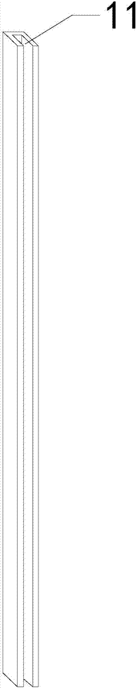
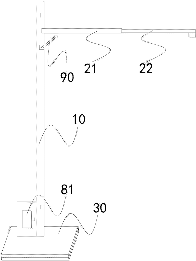
[0044] see figure 1 , figure 2 , image 3 as well as Figure 4 , a monitoring pole of the present invention, comprising a pole body 10, a bracket 20, and a movable base 30, the pole body is arranged on the movable base, the cross section of the pole body is a groove structure 11, and a first gear 40 is also included , the second gear 50, the chain 60, the lifting plate 70 and the power unit, the first gear and the second gear are arranged on the same side of the pole body, and the first gear is arranged directly above the second gear, and the chain It is an endless chain, one side of the chain is arranged in the groove structure of the pole body, the chain is meshed with the first gear and the second gear respectively, the power device includes a first motor 81, and the first motor and the second gear transmission connection; one end of the bracket is fixed on the lifting plate. The first motor is provided with a box to cover the entire first motor, the first motor drives...

Embodiment 2

[0049] In this embodiment, on the basis of Embodiment 1, the single-side vertical rod body is changed into a double-sided vertical rod body, such as Figure 5 As shown, the monitoring rod includes two vertical rod bodies, two lifting plates and two supports; the two sides of the chain are respectively arranged in the groove structures of the two vertical rod bodies, and the two lifting plates 70 are respectively fixed on the sides of the chain. On both sides, one end of the two brackets is respectively fixed on the two lifting plates. Since the chain is on both sides, the left side goes up, the right side goes down; the left side goes down, the right side goes up; therefore, this principle can be used to place two pole bodies, and two sets of monitoring systems can be used at the same time, or an accident can occur in another monitoring system When using another monitoring system, the two systems are connected in series and do not affect each other. The use is more intelligent...

Embodiment 3

[0051] In this embodiment, on the basis of Embodiment 2, the bracket is improved. The bracket includes a front bracket 21, a rear bracket 22, a third gear 23, and a rack 24. The cross section of the front bracket is a groove structure. One end of the front bracket is fixed on the lifting plate, the other end of the front bracket is sleeved on the rear bracket, the rack is arranged in the groove structure of the front bracket, and one end of the rack is fixedly connected with the rear bracket. The third gear meshes with the rack, and the power device further includes a second motor, which is in drive connection with the third gear. In this way, by controlling the forward and reverse rotation of the second motor, the extension and retraction of the rear bracket can be controlled, and there is no need to remove the front and rear brackets to modify the monitoring distance, which saves time and effort, and is more in line with the needs of modern automation.

[0052]During use, th...


PUM


Abstract

The invention relates to a monitoring pole, which comprises a pole body, a bracket, and a movable base. The pole body is arranged on the movable base. The cross section of the pole body is a groove structure. , lifting plate and power device, the first gear and the second gear are arranged on the same side of the pole body, and the first gear is arranged directly above the second gear, the chain is an endless chain, and one side of the chain is arranged on the pole body In the groove structure, the chain meshes with the first gear and the second gear respectively, and the power device includes a first motor, which is connected to the second gear in transmission; one end of the bracket is fixed on the lifting plate. Different from the prior art, the present invention saves time and effort, is safe for manpower, can be adjusted to various heights, solves various special needs, and saves the cost of re-customization. The same bracket can also be adjusted by the motor, which is in line with the development of modern mechanization.

Description

technical field [0001] The invention relates to the technical field of traffic facilities, in particular to a monitoring pole. Background technique [0002] In the Chinese patent with the notification number CN204986262U, a telescopic intelligent monitoring pole that is easy to install is disclosed, including a pole body, a bracket, and a movable base. The pole body is connected to the bracket. There are at least two different heights on the pole body. location of the mounting bracket. The support is composed of at least two sub-supports fixedly connected, and there are at least two installation positions with different telescopic lengths between the sub-supports. The movable base includes a panel, a base plate and a movable sleeve device, the panel is movably connected up and down with the base plate through the movable sleeve device, and the panel is fixedly connected with the pole body. This solution can flexibly adjust the installation height and telescopic distance of...

Claims


Application Information

Patent Timeline
IPC IPC(8): E04H12/18E04H12/24
CPCE04H12/18E04H12/24
Inventor 翁清发
Owner 莆田市荔城区创电维信息技术有限公司
Why Eureka
Try Eureka