Measuring device, Brillouin optical time domain reflectometer and Brillouin frequency shift measurement system

A technology of optical time domain reflectometer and measuring device, which is applied in the direction of the instrument, can solve the problems of measurement value error, frequency drift, measurement error, etc., and achieve the effect of avoiding frequency drift and improving accuracy

Active Publication Date: 2019-03-08
GUANGZHOU BRILLINNOVA TECH CO LTD
View PDF6 Cites 0 Cited by
  • Summary
  • Abstract
  • Description
  • Claims
  • Application Information

AI Technical Summary

Problems solved by technology

However, in the BOTDR system, the laser generating laser pulses has a certain frequency drift due to the influence of temperature or injection current disturbance
However, the Brillouin scattering signal has gone through a period of fiber propagation time. When it returns to the laser pulse injection end and is received for analysis, the frequency of the laser may have drifted, thus making the distribution of Stokes and anti-Stokes light The measurement error of Liouin frequency shift
Although the frequency drift of the laser is small relative to the frequency of the laser (the relative value is generally less than 10 -7 ), but the resulting measurement error is very significant

Method used


Image

  • Measuring device, Brillouin optical time domain reflectometer and Brillouin frequency shift measurement system
  • Measuring device, Brillouin optical time domain reflectometer and Brillouin frequency shift measurement system
  • Measuring device, Brillouin optical time domain reflectometer and Brillouin frequency shift measurement system

Examples


Embodiment Construction

[0049] The technical solutions in the embodiments of the present invention will be clearly and completely described below in conjunction with the accompanying drawings in the embodiments of the present invention. Obviously, the described embodiments are only a part of the embodiments of the present invention, rather than all the embodiments. Based on the embodiments of the present invention, all other embodiments obtained by those of ordinary skill in the art without creative work shall fall within the protection scope of the present invention.

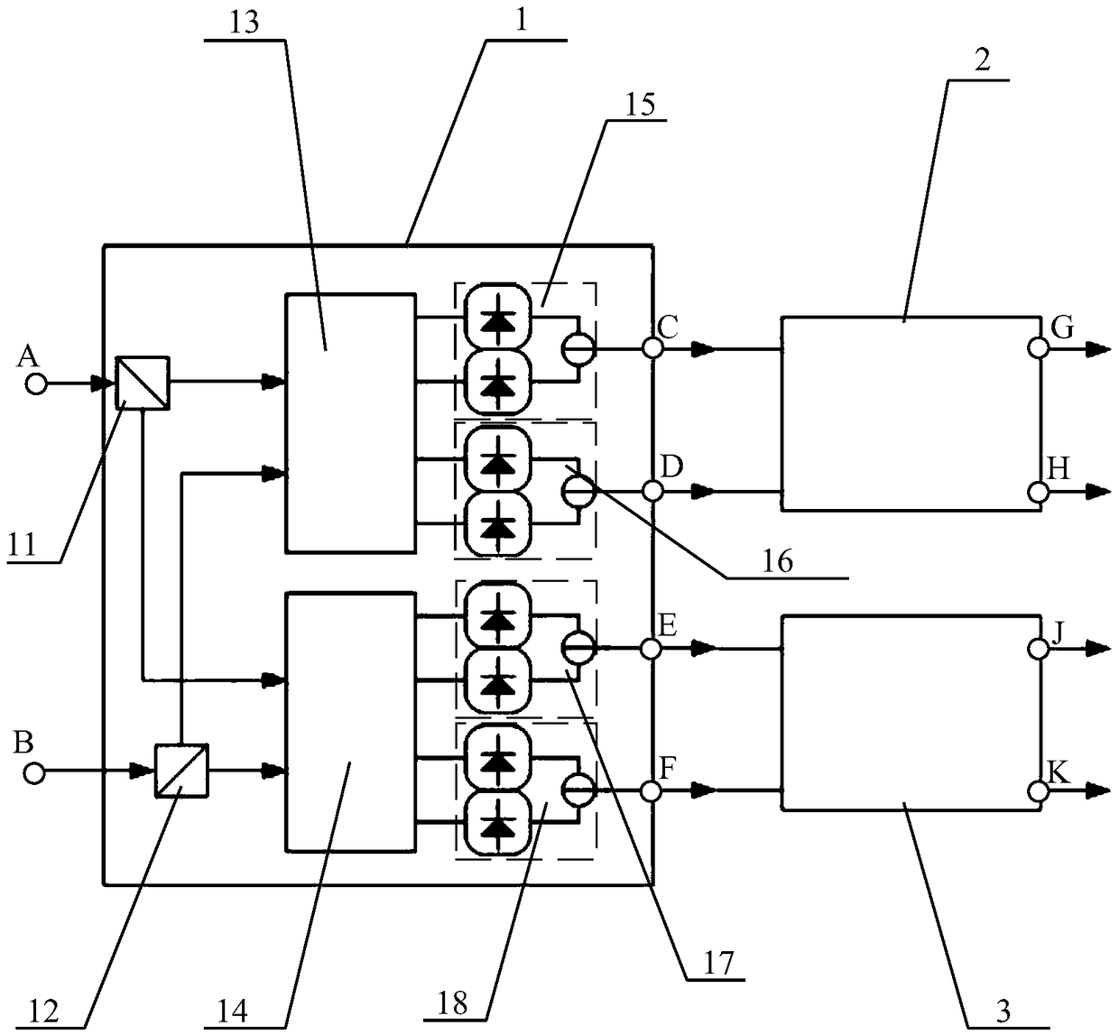
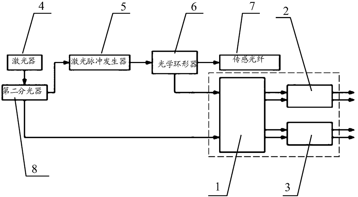
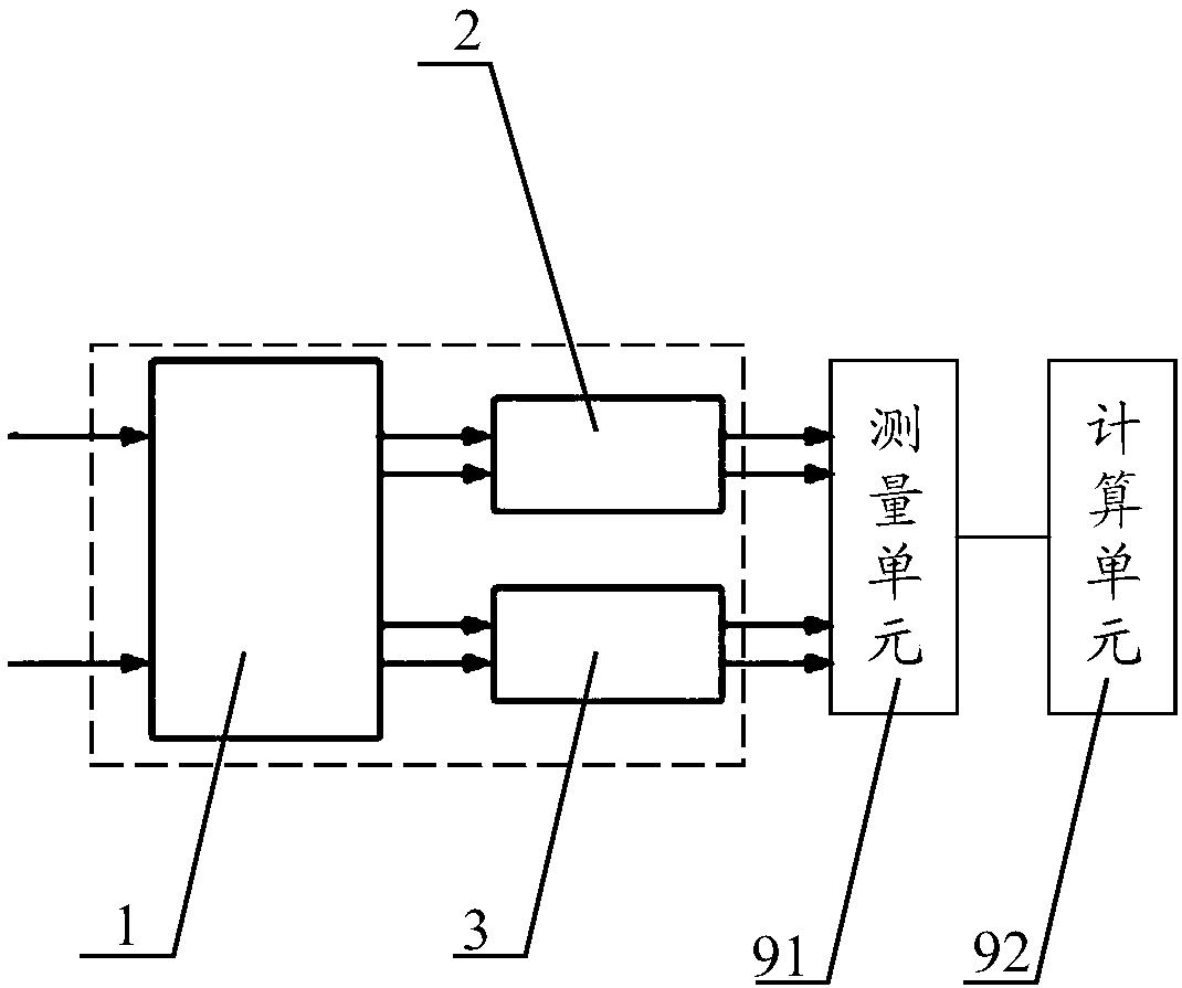
[0050] The purpose of the present invention is to provide a measuring device for Stokes light and anti-Stokes light, by setting a dual polarization coherent receiver, a first radio frequency 90° hybrid coupler and a second radio frequency 90° hybrid coupler, It can process the Brillouin scattered light signal with Stokes light and anti-Stokes light output by the optical circulator of the Brillouin optical time domain reflectometer and the...


PUM


Abstract

The invention discloses a measuring device for Stokes light and anti-Stokes light, a Brillouin optical time-domain reflectometer and a Brillouin frequency shift measurement system. The measuring device comprises the components of a double-polarization coherent receiver which receives a Brillouin scattered light signal that comprises the Strokes light and the anti-Strokes light and receives an intrinsic light signal, and furthermore acquires two X-polarization-state orthogonal electric signals and two Y-polarization-state orthogonal electric signals according to the Brillouin scattered light signal and the intrinsic light signal; a first RF 90-DEG mixing coupler which receives the two X-polarization-state orthogonal electric signals and acquires an X-polarization-state optical signal component of the Strokes light and the X-polarization-state optical signal component of the anti-Strokes light according to the two X-polarization-state orthogonal electric signals; and a second RF 90-DEG mixing coupler which receives the two Y-polarization-state orthogonal electric signals and acquires a Y-polarization-state optical signal component of the Strokes light and the Y-polarization-state optical signal component of the anti-Strokes light according to the two Y-polarization-state orthogonal electric signals. The measuring system, the Brillouin optical time-domain reflectometer and the Brillouin frequency shift measurement system can accurately measure the Strokes light and the anti-Strokes light.

Description

Technical field [0001] The invention relates to the technical field of distributed optical fiber sensing, in particular to a measurement device for Stokes light and anti-Stokes light, a Brillouin optical time domain reflectometer and a Brillouin frequency shift measurement system. Background technique [0002] Distributed optical fiber sensing technology can measure the temperature or perturbation of the physical quantity to be measured along a section of sensing fiber, and can locate the position of the physical quantity to be measured, so as to obtain the distribution of the physical quantity to be measured along the sensing fiber. Because the sensing optical fiber in the distributed optical fiber sensing technology generally uses an ordinary optical fiber, the cost is low, and its sensing distance is long, so it has received extensive attention. [0003] Distributed optical fiber sensing technology mainly uses the scattering effect of laser in optical fiber to perform sensing me...

Claims


Application Information

Patent Timeline
Patent Type & Authority Patents(China)
IPC IPC(8): G01J11/00
CPCG01J11/00
Inventor 程凌浩关柏鸥梁浩李威刘伟民周黎明
Owner GUANGZHOU BRILLINNOVA TECH CO LTD
Why Eureka
Try Eureka