Tapered optical fiber based high-power optical fiber end cap

A tapered fiber and fiber end technology, applied in the field of fiber lasers, can solve the problems of lowering the threshold of nonlinear effects and increasing the interaction distance of nonlinear effects, so as to improve the cooling effect, reduce the back light feedback, and improve the safety. and the effect of workplace stability

Active Publication Date: 2017-07-18
NAT UNIV OF DEFENSE TECH
View PDF7 Cites 15 Cited by
  • Summary
  • Abstract
  • Description
  • Claims
  • Application Information

AI Technical Summary

Problems solved by technology

The thresholds of these two nonlinear effects are closely related to the length of the fiber in the fiber optic system. After the end cap is added, due to the increase in the overall fiber length, the interaction distance of the nonlinear effects i...

Method used


Image

  • Tapered optical fiber based high-power optical fiber end cap
  • Tapered optical fiber based high-power optical fiber end cap
  • Tapered optical fiber based high-power optical fiber end cap

Examples


Embodiment 1

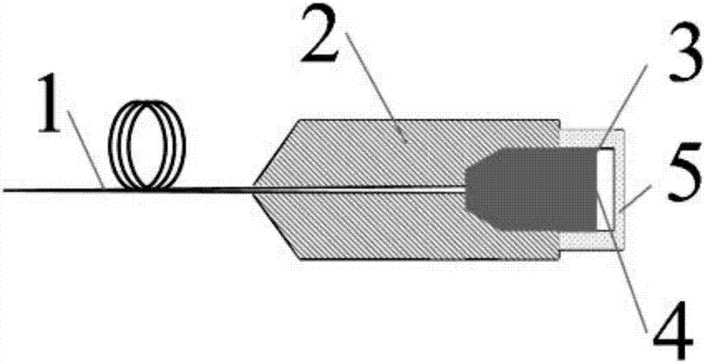
[0033] Example 1: See figure 1 , a high-power fiber end cap based on a single-clad tapered optical fiber, comprising a single-clad tapered optical fiber 1, a quartz block 3 and an end cap shell 2, the large end of the single-clad tapered optical fiber 1 from the end cap shell 2 One end penetrates into the inside of the end cap shell 2 and is fixed on the end cap shell 2. The other end of the end cap shell 2 is provided with a cavity for the quartz block 3 to extend into. The quartz block 3 extends into the inside of the end cap shell. One end is a truncated conical end, the end of the quartz block 3 extending out of the end cap shell 2 is cylindrical and the end surface of the cylindrical end of the quartz block 3 extending out of the end cap shell 2 is coated with an anti-reflection film 4; on the end cap Inside the shell 2, the frustum-shaped end of the quartz block 3 is fused with the large end of the tapered optical fiber 1, and an output end cap protection window is set ...

Embodiment 2

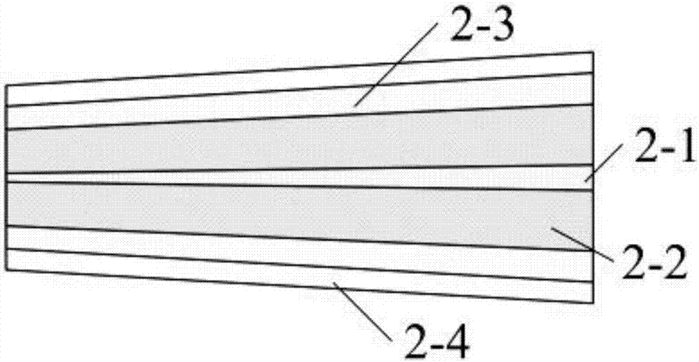
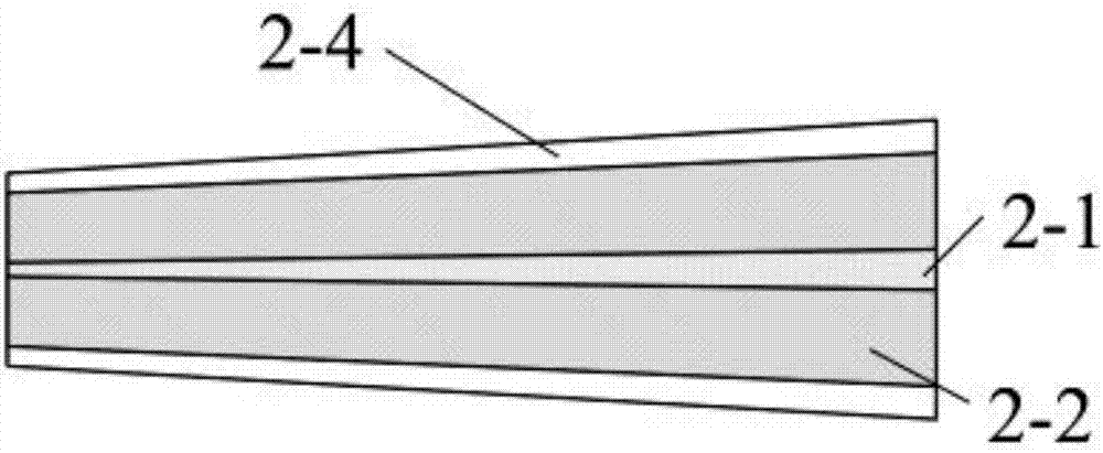
[0036] Example 2: see Figure 6 , a schematic diagram of a high-power fiber end-cap structure based on a double-clad tapered fiber. For the double-clad tapered optical fiber 6, one end of the double-clad tapered optical fiber 6 inserted into the end cap shell 2 needs to remove its coating 2-4 before stretching into the end cap shell 2 inside, that is, stretch into the end cap The double-clad tapered optical fiber 6 inside the housing 2 is a section of optical fiber 7 with the coating removed. The surface of the optical fiber 7 from which the coating layer has been removed is coated and cured with an ultraviolet curing adhesive 8 to form a cladding optical stripper.

[0037] Flowing cooling liquid is arranged inside the end cap housing 2 to assist heat dissipation. In this embodiment, the inside of the end cap housing 2 is a cavity 11 . The large end of the processed double-clad tapered optical fiber 6 is penetrated from one end of the end cap shell 2 into the inner cavity o...


PUM

PropertyMeasurementUnit
Diameteraaaaaaaaaa
Diameteraaaaaaaaaa
Diameteraaaaaaaaaa

Abstract

A tapered optical fiber based high-power optical fiber end cap comprises a tapered optical fiber, a quartz block and an end cap housing, wherein a big end of the tapered optical fiber passes through one end of the end cap housing into the end cap housing and then is fixed to the end cap housing; a chamber in which the quartz block extends is formed in the other end of the end cap housing; the end, extending into the end cap housing, of the quartz block is a tapered table shaped end head; the end, extending out of the end cap housing, of the quartz block is cylindrical; an anti-reflection film coats the surface of the cylindrical end, extending out of the end cap housing, of the quartz block; the tapered table shaped end head of the quartz block is fused with the big end of the tapered optical fiber; an output end cap protecting window is arranged on the end cap housing section at the end, extending out of the end cap housing, of the quartz block; the cylindrical end, extending out of the end cap housing, of the quartz block is closed through the output end cap protecting window. The tapered optical fiber based high-power optical fiber end cap is simple in structure, and capable of improving the laser power bearing capacity of the optical fibers, and remains high laser beam quality while effectively inhibiting nonlinear effect.

Description

technical field [0001] The invention belongs to the field of fiber laser and relates to a high-power fiber end cap based on a tapered fiber. Background technique [0002] In the late 1980s, with the maturity of optical fiber manufacturing technology and the development of solid-state lasers, fiber lasers began to become a research hotspot, and with the maturity of double-clad fiber and cladding pumping technology, high-power fiber lasers began Make breakthrough progress. Because fiber lasers have the advantages of small size, light weight, convenient thermal management, and good beam quality, in recent years, high-power fiber lasers with fiber output have been used in optical communications, material processing, medical diagnosis and treatment, information storage, laser printing, and laser measurement and control. , laser spectroscopy and nonlinear frequency conversion and other fields have been widely used. [0003] As the output power of fiber lasers continues to increa...

Claims


Application Information

Patent Timeline
IPC IPC(8): G02B6/24G02B6/26G02B6/44
CPCG02B6/241G02B6/262G02B6/4439
Inventor 王小林史尘杨保来张汉伟粟荣涛陶汝茂马鹏飞周朴许晓军司磊陈金宝刘泽金
Owner NAT UNIV OF DEFENSE TECH
Why Eureka
Try Eureka