Time synchronization system and method for network instruments

A time synchronization system and time synchronization technology, applied in time division multiplexing systems, multiplexing communications, electrical components, etc., can solve problems such as network transmission efficiency decline, time synchronization cannot be completed, and network transmission cannot be guaranteed. Achieve the effect of reducing hardware expenses, reducing data transmission interference, and avoiding long waiting times

Inactive Publication Date: 2017-07-18
NORTHWESTERN POLYTECHNICAL UNIV +1
View PDF3 Cites 9 Cited by
  • Summary
  • Abstract
  • Description
  • Claims
  • Application Information

AI Technical Summary

Problems solved by technology

The existing network instrument system that uses Ethernet as the connection bus generally adopts a planar structure, and the control center and all network instruments are connected to the communication bus. Refer to figure 1 , figure 1 It is a schematic diagram of the structural connection of the time synchronization system used in the prior art. This structure has the following disadvantages: first, each network instrument only needs to transmit the measurement data to the control center, and does not need to be transmitted to other instruments. When the control center uploads the measurement data, it should try not to affect the communication between other instruments and the control center. However,

Method used


Image

  • Time synchronization system and method for network instruments
  • Time synchronization system and method for network instruments
  • Time synchronization system and method for network instruments

Examples


Embodiment 1

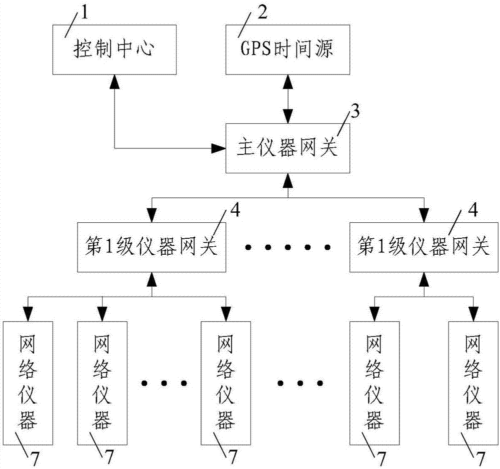
[0056] Such as image 3 As shown, in this embodiment, the N=1, the branch instrument gateway is composed of a layer 1 instrument gateway, the layer 1 instrument gateway includes at least two first-level instrument gateways 4, and the main instrument gateway 3 is the first level The first-level instrument gateway of the instrument gateway 4, the first-level instrument gateway 4 communicates with the main instrument gateway 3 and the network instrument 7 through the Ethernet communication module.

[0057] Ethernet is the most common communication protocol standard adopted by the existing local area network. It has the characteristics of mature technology, low cost, high reliability, high speed and good openness, and is widely used.

[0058] In actual installation and use, the number of network instruments 7 is relatively large, and the synchronization of at least two first-level instrument gateways 4 is controlled through the main instrument gateway 3, and at least two first-lev...

Embodiment 2

[0060] Such as figure 2 As shown, the difference between this embodiment and Embodiment 1 is that the N=2, the branch instrument gateway is composed of two-layer instrument gateways, and the first-layer instrument gateway in the two-layer instrument gateway includes at least two The first-level instrument gateway 4, the second-level instrument gateway in the second-level instrument gateway includes at least two second-level instrument gateways 5, the first-level instrument gateway 4 is the first-level instrument gateway of the second-level instrument gateway 5 , the first-level instrument gateway 4 communicates with the main instrument gateway 3 through an Ethernet communication module, the second-level instrument gateway 5 is controlled and synchronized by the first-level instrument gateway connected to the second-level instrument gateway 5, and the second-level instrument gateway 5 communicate with the network instrument 7 through the Ethernet communication module.

[0061...

Embodiment 3

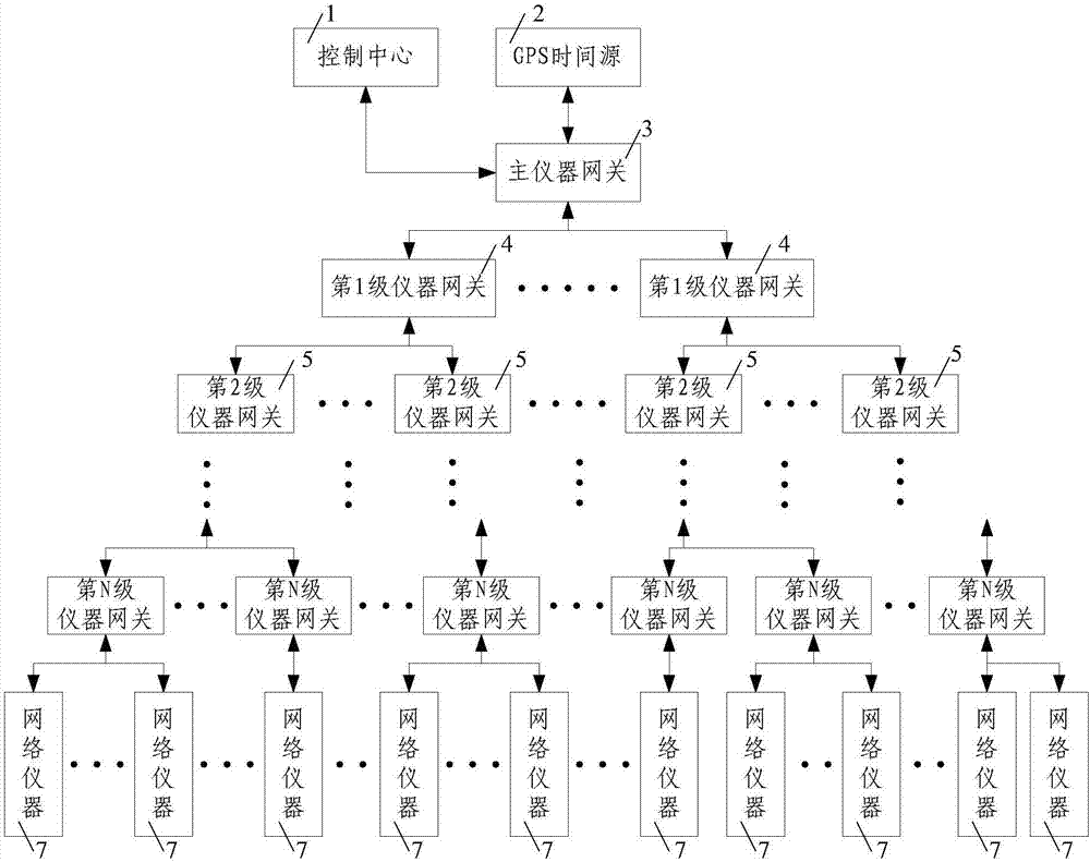
[0063] Such as image 3 As shown, the difference between this embodiment and Embodiment 2 is that the N=3, the branch instrument gateway is composed of three layers of instrument gateways, and the first layer of instrument gateways in the three layers of instrument gateways includes at least two A level 1 instrument gateway 4, a level 2 instrument gateway in the level 3 instrument gateways includes at least two level 2 instrument gateways 5, a level 3 instrument gateway in the level 3 instrument gateways includes at least two level 3 instrument gateways Level 1 instrument gateway 6, level 1 instrument gateway 4 is the first level instrument gateway of level 2 instrument gateway 5, level 2 instrument gateway 5 is the first level instrument gateway of level 3 instrument gateway 6, level 1 instrument gateway 4 Communicate with the main instrument gateway 3 through the Ethernet communication module, the second-level instrument gateway 5 is controlled and synchronized by the first-...


PUM


Abstract

The invention discloses a time synchronization system and method for network instruments. The system comprises a tree-shaped instrument gateway, a control center, and the network instruments, wherein the control center is connected with a root node of the tree-shaped instrument gateway; the network instruments are connected with leaf nodes of the tree-shaped instrument gateway; the tree-shaped instrument gateway is composed of a main instrument gateway positioned at a root node position of the tree-shaped instrument gateway, and branch instrument gateways connected with the main instrument gateway; the control center communicates with the main instrument gateway via an Ethernet communication module; and the main instrument gateway is connected with a GPS time source used for synchronizing a local clock; and the method comprises the following steps: 1, synchronizing a time of the main instrument gateway; 2, synchronizing a time of an ith layer of the instrument gateways; 3, repeating the step 2 for N times till a time synchronization process of an Nth layer of the instrument gateways is finished; and 4, synchronizing a time of the network instruments. According to the time synchronization system and method disclosed by the invention, the design is original, the data transmission interference among the network instruments is reduced, and the network transmission efficiency and the time synchronization precision are improved.

Description

technical field [0001] The invention belongs to the technical field of time synchronization, and in particular relates to a time synchronization system and method for network instruments. Background technique [0002] The rapid development of computer technology, microelectronics technology and network technology has continuously promoted the transformation of measuring instruments towards digitalization and intelligence. The working mode of measuring instruments has also developed from the early independent work of a single instrument to the collaborative work of multiple intelligent instruments. Nowadays, in some key fields, such as navigation, aerospace, national defense, etc., the large-scale automatic test system used may contain hundreds or thousands of intelligent instruments. In order to ensure the efficient and stable operation of the entire test system, the connection bus between these instruments is particularly important. The existing network instrument system th...

Claims


Application Information

Patent Timeline
IPC IPC(8): H04J3/06
CPCH04J3/0644
Inventor 韩刚马素刚李有谋李辉
Owner NORTHWESTERN POLYTECHNICAL UNIV
Why Eureka
Try Eureka