Lumbar vertebra posterior-lateral minimally invasive decompression and fusion system

A posterolateral and lumbar technology, applied in the field of lumbar posterolateral minimally invasive decompression and fusion system, can solve the problems of increased surgical complexity, surgical risk and surgical cost, easy backward prolapse of implanted intervertebral fusion device, and bone graft bed treatment Difficulties and other problems, to achieve the effect of improving the fusion effect, good fusion effect, and reasonable shape and structure settings

Active Publication Date: 2017-07-21
SECOND AFFILIATED HOSPITAL SECOND MILITARY MEDICAL UNIV
View PDF11 Cites 4 Cited by
  • Summary
  • Abstract
  • Description
  • Claims
  • Application Information

AI Technical Summary

Problems solved by technology

Although this traditional surgical method has good clinical effect, it has the following disadvantages: 1. The operation is cumbersome, and the intervertebral space is processed in turn with nucleus pulposus forceps, spreader, scraper, and reamer. This step usually requires 3-4 cycles; 2. It is difficult to handle the bone graft bed in young patients and patients with osteoporosis; 3. If the implanted intervertebral fusion device is too small, it will easily prolapse backwards; if it is too large, it will easily damage the nerve and cause postoperative axial pain; 4. The posterior approach For intervertebral fusion, it is necessary to remove part of the appendage bony stru

Method used


Image

  • Lumbar vertebra posterior-lateral minimally invasive decompression and fusion system
  • Lumbar vertebra posterior-lateral minimally invasive decompression and fusion system
  • Lumbar vertebra posterior-lateral minimally invasive decompression and fusion system

Examples


Embodiment 1

[0064] The posterolateral minimally invasive decompression and fusion system of the lumbar spine of the present invention comprises a guide 1 , a protective sleeve 2 , a trephine 3 , a holder 4 and a fusion device 5 .

[0065] guide

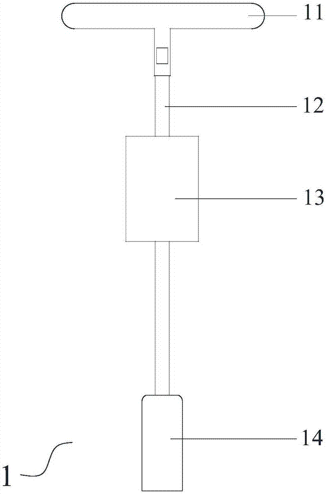
[0066] See figure 1 , figure 1 is the front view of the director. The guide is provided with a guide handle 11 , a guide connecting rod 12 , a guide block 13 and a brace head 14 . The guide handle 11 is "T" shaped, and the guide link 12 is a round bar with an upper end connected to the guide handle 11 . The guide block 13 is a cylinder and is arranged on the guide link 12 with the guide link 12 as the central axis. The opening 14 is connected to the lower end of the guide connecting rod 12; the opening 14 is a cuboid as a whole.

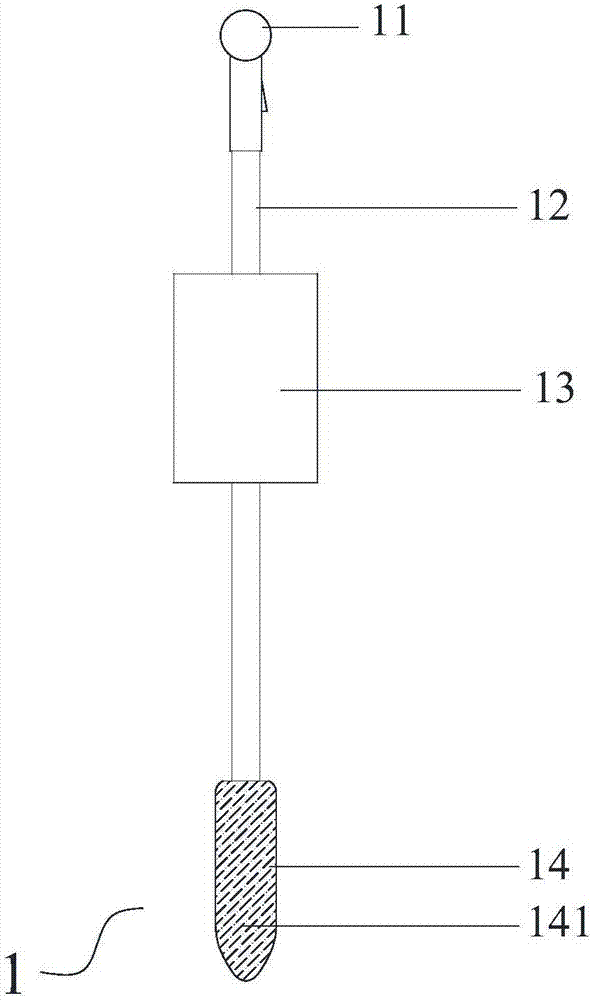
[0067] See figure 2 , figure 2 is the right view of the director. The two larger sidewalls of the propping head 14 gradually meet at the lower end so that the lower end surface is a narrower curved surface; ...


PUM

PropertyMeasurementUnit
Lengthaaaaaaaaaa
Widthaaaaaaaaaa
Thicknessaaaaaaaaaa

Abstract

The invention relates to a lumbar vertebra posterior-lateral minimally invasive decompression and fusion system. The lumbar vertebra posterior-lateral minimally invasive decompression and fusion system comprises a guider, a protective sleeve, a trephine, a holder and a fusion cage; the guider is provided with a guider handle, a guider connecting rod detachably connected with the guider handle, a guide block arranged on the guider connecting rod and an opening head connected to the lower end of the guider connecting rod; a baffle and an anchoring nail arranged on the protective sleeve; a trephine handle and a work sleeve with the jagged lower edge are arranged on the trephine; the guide block is sleeved with a work sleeve, and the work sleeve is sleeved with the protective sleeve; a holder handle and holder connecting rod connected with the holder handle and provided with a drainage channel in side are arranged on the holder; a fusion cage body is arranged on the fusion cage, a fastening channel and a nail path for assembling and fixing nails are formed in the fusion cage body, and the holder connecting rod and the fusion cage are connected in a fastened mode. The device is used for lumbar vertebra decompression and is better in fusion effect, easier to operate, minimally invasive and small in damage.

Description

technical field [0001] The invention relates to the technical field of medical devices, in particular to a posterolateral minimally invasive decompression and fusion system for the lumbar spine. Background technique [0002] Lumbar fusion is a basic technique for the treatment of lumbar disorders, applicable to: vertebral destructive diseases, such as spinal tuberculosis or spinal tumors, which cause damage to one or several vertebrae; loss of spinal stability, such as spinal injury, degeneration, vertebral Instability of the spine from destruction or surgery; displacement or slippage with pain and dysfunction; prevention or correction of deformity; cooperation with corrective surgery. [0003] In lumbar fusion, the lumbar intervertebral joints are osseointegrated through anterior and posterior lumbar surgery in facet joints, intertransverse process bone grafts, and intervertebral bone grafts, thereby establishing and maintaining lumbar spine stability. Bone graft fusion pl...

Claims


Application Information

Patent Timeline
IPC IPC(8): A61F2/44A61F2/46A61B17/02A61B17/16
CPCA61B17/025A61B17/1671A61B17/1695A61B2017/0256A61B2017/0262A61F2/4455A61F2/4611A61F2002/4635A61F2002/4687
Inventor 孙璟川史建刚
Owner SECOND AFFILIATED HOSPITAL SECOND MILITARY MEDICAL UNIV
Why Eureka
Try Eureka