Continuous moldless forming device and method for metal bellows

A metal bellows, dieless forming technology, applied in the storage device, feeding device, positioning device and other directions, can solve the problem of inability to realize the processing and forming of long-distance bellows in the axial direction, and achieve simple structure, low cost, and widen application. field effect

Active Publication Date: 2019-03-15
NORTHEASTERN UNIV LIAONING
View PDF4 Cites 0 Cited by
  • Summary
  • Abstract
  • Description
  • Claims
  • Application Information

AI Technical Summary

Problems solved by technology

[0005] However, since the two ends of the metal round tube are fixed on the driving plate by the chuck in the metal bellows dieless forming process, the length of the metal round tube used in the forming process is limited, so that the axial long distance cannot be realized. Processing and forming of bellows

Method used


Image

  • Continuous moldless forming device and method for metal bellows
  • Continuous moldless forming device and method for metal bellows
  • Continuous moldless forming device and method for metal bellows

Examples


Embodiment 1

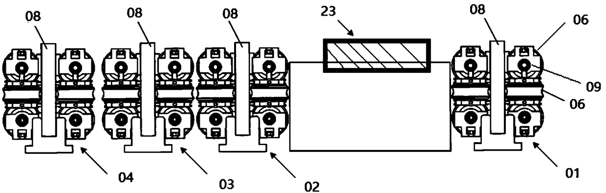
[0052] The continuous moldless forming device of metal bellows in this embodiment includes: at least one first metal pipe feeding assembly (such as figure 1 No. 1 roll box 01 structure shown in), metal tube corrugation forming assembly, at least one third metal tube feeding assembly (such as figure 1 structure of No. 2 roll box 02 and No. 3 roll box 03) and at least one second metal tube feed assembly (such as figure 1The structure of No. 4 roller box 04 shown in);

[0053] In this embodiment, the first metal pipe feeding assembly is used to feed the metal pipe at the first feeding speed; the second metal pipe feeding assembly and the third metal pipe feeding assembly are used to feed the metal pipe at the second feeding speed Metal tube; the first feed rate is greater than the second feed rate. The axial compression force of the metal tube during the corrugation process can be provided by means of different feed speeds.

[0054] The metal pipe feeding assembly in this embo...

Embodiment 2

[0069] The following combination Figure 1 to Figure 3 A continuous dieless forming device for metal bellows will be described in detail.

[0070] The continuous moldless forming device of metal bellows in this embodiment includes: a first metal pipe feeding assembly (namely No. 1 roller box 01), a metal circular pipe corrugation forming assembly 23, two third metal pipe feeding assemblies ( Such as figure 1 No. 2 roll box 02, No. 3 roll box 03), a second metal tube feed assembly.

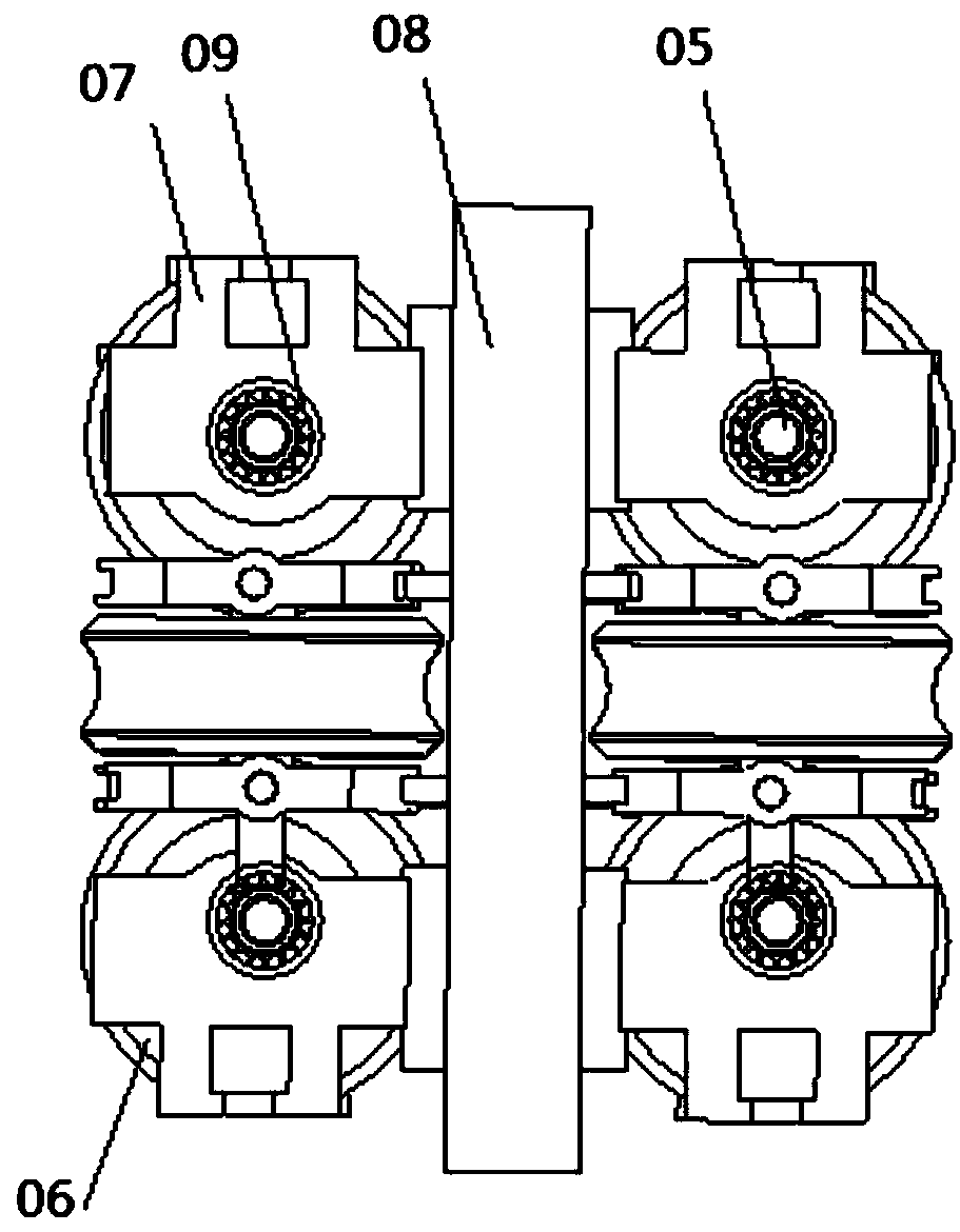
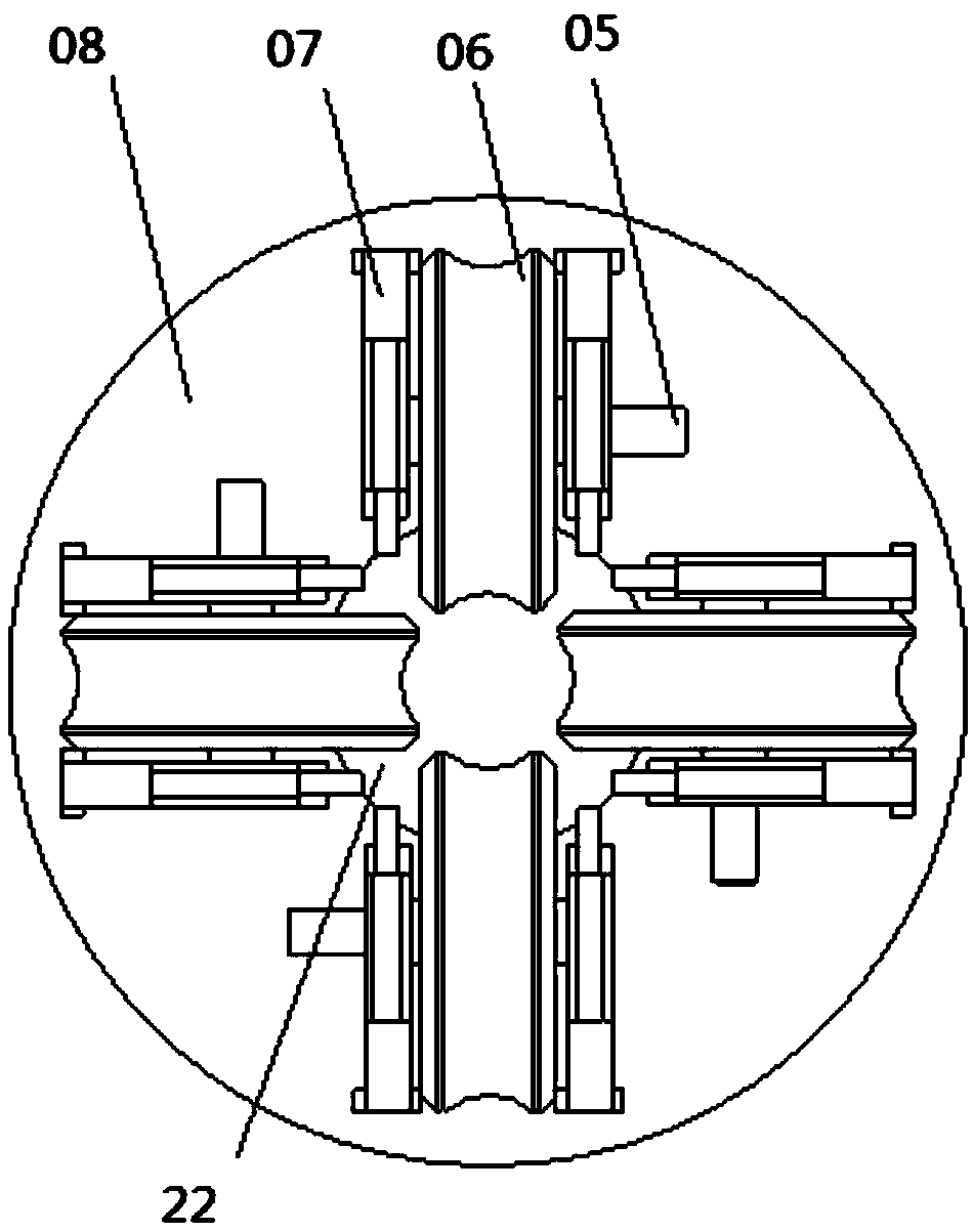
[0071] No. 1 roll box 01 to No. 4 roll box 04 are respectively provided with their own feed end and discharge end; wherein, the feed end of each roll box corresponds to a group of evenly distributed nip rollers, and the discharge end of each roll box Corresponding to a group of evenly distributed pinch rollers. Along the feeding direction of the metal pipe, there are uniformly distributed pinch rollers 11 at the feed end of the No. 1 roll box, uniformly distributed pinch rolls 12 at the discharg...

Embodiment 3

[0095] This embodiment provides a method for forming the continuous moldless forming device described in Embodiment 1, the method includes:

[0096] Step A01, passing one end of the metal pipe sequentially through the first metal pipe feeding assembly, the metal pipe forming assembly, the third metal pipe feeding assembly and the second metal pipe feeding assembly, and making the first metal pipe feeding assembly and the second metal pipe feeding assembly Two metal tube feed assemblies grip the metal tube.

[0097] At this time, the first metal pipe feeding assembly and the second metal pipe feeding assembly are in a clamped state.

[0098] Step A02, the metal tube corrugation forming component performs circumferential heating on a selected local heating position on the metal tube, forms an annular heating area on the metal tube, and simultaneously performs circumferential heating on both sides of the annular heating area on the metal tube. cool down.

[0099] In this step, ...


PUM


Abstract

The invention provides a continuous no-mold forming device and method of a metal corrugated pipe. The device comprises at least one first metal pipe feeding assembly, a metal pipe corrugation forming assembly, at least one third metal pipe feeding assembly and at least one second metal pipe feeding assembly, wherein the first metal pipe feeding assemblies, the metal pipe corrugation forming assembly, the third metal pipe feeding assemblies and the second metal pipe feeding assemblies are sequentially arranged in the metal pipe feeding direction. The first metal pipe feeding assemblies are used for feeding metal pipes at a first feeding speed, the second metal pipe feeding assemblies and the third metal pipe feeding assemblies are used for feeding the metal pipes at a second feeding speed, and the first feeding speed is larger than the second feeding speed. The metal pipe corrugation forming assembly is used for forming corrugation on the metal pipe wall. The device can achieve production of the axial long-distance metal corrugated pipe with continuous or non-continuous corrugation.

Description

technical field [0001] The invention relates to a technology of dieless forming of metal pipes, in particular to a continuous dieless forming device and method for metal corrugated pipes. Background technique [0002] As a special special-shaped pipe, metal bellows has attracted much attention because of its special functions. Metal bellows have axial, angular and lateral deformation capabilities, and have the characteristics of stress deformation and geometric shape periodic changes, as well as the ability to compensate for thermal deformation of pipelines, shock absorption, and absorption of pipeline settlement deformation. Therefore, metal bellows It has been widely used in petrochemical, instrumentation, aerospace, chemical, electric power, cement, metallurgy, machinery, transportation, nuclear energy and other industries, and is used to manufacture various sensitive components, compensation components, flexible connectors and heat exchange components. [0003] In recen...

Claims


Application Information

Patent Timeline
Patent Type & Authority Patents(China)
IPC IPC(8): B21D15/06B21D37/16B21D43/08
CPCB21D15/06B21D37/16B21D43/08
Inventor 张自成申玉鑫许艳云
Owner NORTHEASTERN UNIV LIAONING
Why Eureka
Try Eureka