
An integrated high-rigidity light-weight photovoltaic cell module and photovoltaic shutters

A technology of photovoltaic cells and high stiffness, which is applied in the direction of photovoltaic power generation, photovoltaic modules, electrical components, etc., can solve the problems of low stiffness of blade plates, affect service life, and high cost of use, and achieve easy manufacturing and assembly, protection of bus wires, and lightening effect of weight

Active Publication Date: 2018-01-26
SHANGHAI MODIER METAL STRUCTURE TECH CO LTD
View PDF3 Cites 0 Cited by
  • Summary
  • Abstract
  • Description
  • Claims
  • Application Information

AI Technical Summary

Problems solved by technology

[0003] Existing louver blade-type photovoltaic power generation modules have disadvantages such as low blade stiffness, easy deformation, and heavy weight, which affect the service life and lead to high product use costs

Method used


Image

  • An integrated high-rigidity light-weight photovoltaic cell module and photovoltaic shutters
  • An integrated high-rigidity light-weight photovoltaic cell module and photovoltaic shutters
  • An integrated high-rigidity light-weight photovoltaic cell module and photovoltaic shutters

Examples


Embodiment 1

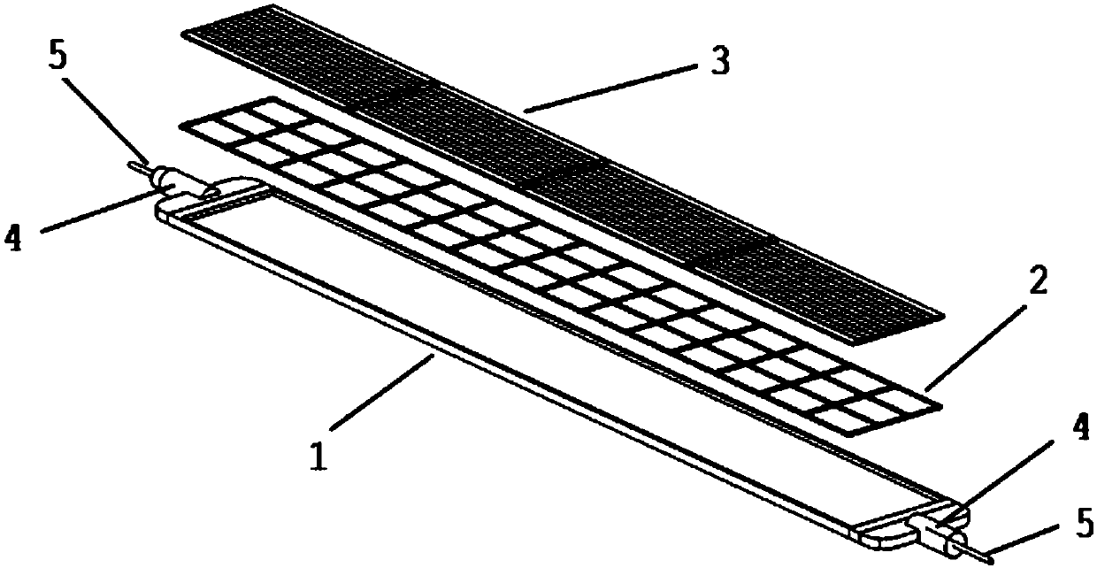
[0033] Such as figure 1 As shown, an integrated high-rigidity light-weight photovoltaic cell assembly includes photovoltaic blades arranged in a louver structure as a whole. The photovoltaic blades have a transmission shaft 4 and a bus wire 5, and the transmission shaft 4 is used for fixing and rotating the photovoltaic blades. , a single photovoltaic blade is a laminated composite structure, including a composite plastic layer 1 and a strip-shaped photovoltaic cell sheet 3 bonded to each other, a transmission shaft 4 and a bus wire 5 are arranged at both ends of the strip-shaped photovoltaic cell sheet 3, and the composite plastic layer 1 is injection-molded An integrally formed plastic layer, the prestressed steel wire mesh 2 is connected to the strip-shaped photovoltaic cells 3 by bonding.

[0034] The components of the composite plastic layer 1 are: PC+ABS.

[0035] Composite plastic layer 1 has structural ribs 6, and the front view shape of structural ribs 6 is as follow...

Embodiment 2

[0040] Different from Embodiment 1, the structural ribs 6 also include oblique ribs 63, the number of transverse ribs 61 is one, and the longitudinal ribs 62 divide the surface of the composite plastic layer 1 into a plurality of square grids, and the oblique ribs 63 are arranged on each square grid. The diagonal position of the grid. Specific as image 3 shown. This structure also achieves better strength.

[0041] All the other are identical with embodiment 1.

Embodiment 3

[0043] Different from Embodiment 1, the structural rib 6 is corrugated, and the corrugated stripes are parallel to the length direction of the photovoltaic blade. Specific as Figure 5 shown. The advantage of this structure is that it is easy to clean the blades, and the strength can also meet the requirements.

[0044] All the other are identical with embodiment 1.


PUM


Abstract

The invention relates to an integrated high-rigidity light photovoltaic cell component, which comprises photovoltaic blades which are in shutter structure arrangement on the whole, wherein the photovoltaic blades are provided with transmission shafts (4) and bus wires (5); the transmission shafts (4) are used for fixing and rotating the photovoltaic blades; single photovoltaic blade is of a laminated composite structure and comprises a composite a composite plastic layer (1), a prestressed steel wire mesh (2) and a bar photovoltaic cell (3) which are sequentially arranged; the transmission shafts (4) and the bus wires (5) are arranged at two ends of the corresponding bar photovoltaic cells (3); each composite plastic layer (1) is a plastic layer which is integrally molded in an injection manner; and each internal prestressed steel wire mesh (2) is connected with the corresponding bar photovoltaic cell (3). Compared with the prior art, the integrated high-rigidity light photovoltaic cell component has the advantages of being light, high in rigidity, low in warping degree and high in weather resistance, and integrates sun-shading and power generation.

Description

technical field [0001] The invention relates to a photovoltaic cell assembly, in particular to an integrated high-rigidity and light-weight photovoltaic cell assembly and a photovoltaic shutter. Background technique [0002] BIPV is mainly used in distributed photovoltaic power generation, so that the photovoltaic system and the appearance of the building are coordinated and integrated with each other, and the facade of the building is fully utilized without changing the shape of the facade or increasing the maintenance of structural materials. This product increases the functions of power generation and sunshade. The core product of building integrated photovoltaics is photovoltaic power generation components. Existing photovoltaic power generation components are generally in the form of louver blades, which are assembled with glass windows. They have a beautiful appearance and can integrate shading and power generation functions. [0003] Existing louver blade-type photov...

Claims


Application Information

Patent Timeline
Patent Type & Authority Patents(China)
IPC IPC(8): H01L31/049H01L31/05H02S40/36
CPCH01L31/049H01L31/0504H02S40/36Y02A30/14Y02E10/50
Inventor 袁文堂
Owner SHANGHAI MODIER METAL STRUCTURE TECH CO LTD
Learn More