Low-dragging automotive disc floating brake and braking method thereof

A technology for brakes and automobiles, applied in the direction of brake types, axial brakes, brake actuators, etc., can solve the problems of contact drag between two friction plates and brake discs, reduce drag energy loss, reduce wear, Solve the effect of easy wear

Inactive Publication Date: 2017-07-21
WUHAN UNIV OF TECH
4 Cites 11 Cited by

AI-Extracted Technical Summary

Problems solved by technology

[0004] The main purpose of the present invention is to provide a low drag automobile disc floating brake and its braking method, aiming to solve t...

Method used

Further, this low-drag automobile disc-type floating brake also includes the sealing ring 31 that is sleeved on the piston rod 30 afterbody, to improve the working reliability of this low-drag automobile disc-type floating brake, avoid the situation of oil leakage .
[0024] Further, the low-drag automobile disc floating brake also includes a sound-absorbing sheet 90 fixed on the first lining 50 and the second lining 60, and the sound-absorbing sheet 90 is fixed on the first lining 50 and the second lining 6...

Abstract

The invention discloses a low-drag automobile disc floating brake, which comprises a mounting bracket, a floating caliper body, a piston rod, a guide pin, a first lining, a second lining, a first friction plate and a second friction plate, and the floating The caliper body is installed on the mounting bracket through the guide pin, the guide pin is covered with an elastic piece, the floating caliper body is provided with a piston cylinder, the first oil port and the second oil port, the piston rod is accommodated in the piston cylinder, and the piston rod includes a head The head of the piston rod divides the piston cylinder into a left chamber and a right chamber, one end of the piston rod tail is accommodated in the right chamber, and the other end of the piston rod tail is fixed with the first lining, the second The two linings are fixed on the floating caliper body, and the first lining and the second lining are respectively fixed with a first friction plate and a second friction plate. The low-drag automotive disc-type floating brake proposed by the invention solves the problem of drag caused by the two friction plates still in contact with the brake disc after the release of the traditional floating-caliper brake.

Application Domain

Technology Topic

Image

  • Low-dragging automotive disc floating brake and braking method thereof

Examples

  • Experimental program(1)

Example Embodiment

[0018] It should be understood that the specific embodiments described here are only used to explain the present invention, but not to limit the present invention.
[0019] It should be noted that in the description of the present invention, the terms "horizontal", "vertical", "upper", "lower", "front", "rear", "left", "right", "vertical", The orientation or positional relationship indicated by "horizontal", "top", "bottom", "inner", "outer", etc. is based on the orientation or positional relationship shown in the drawings, and is only for the convenience of describing the present invention and simplifying the description, and It does not indicate or imply that the pointed device or element must have a specific orientation, be constructed and operated in a specific orientation, and therefore cannot be understood as a limitation of the present invention. In addition, the terms "first", "second", etc. are only used for descriptive purposes, and cannot be understood as indicating or implying relative importance.
[0020] The present invention provides a low-drag automobile disc floating brake.
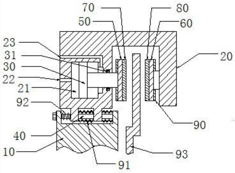
[0021] Reference figure 1 In this preferred embodiment, a low-drag automotive disc floating brake includes a mounting bracket 10, a floating caliper body 20, a piston rod 30, a guide pin 40, a first lining 50, a second lining 60, and a first The friction plate 70 and the second friction plate 80, in which,
[0022] The floating caliper body 20 can be movably installed on the mounting bracket 10 through the guide pin 40. The floating caliper body 20 is arranged on both sides of the brake disc 93. The guide pin 40 is sleeved with an elastic member 92 to make the floating caliper body 20 relative to The mounting bracket 10 can be reset. The floating clamp body 20 is provided with a piston cylinder 21 and a first oil port 22 and a second oil port 23 communicating with the piston cylinder 21. The piston rod 30 is housed in the piston cylinder 21 and can be When moving, the piston rod 30 includes a head contained in the piston cylinder 21 and a tail that penetrates the floating clamp body 20. The head of the piston rod 30 separates the piston cylinder 21 into a left chamber and a right chamber. The side chamber communicates with the first oil port 22, the right chamber communicates with the second oil port 23, one end of the tail of the piston rod 30 is accommodated in the right chamber, and the other end of the tail of the piston rod 30 is fixed with a first lining 50 , The second lining 60 is fixed on the floating caliper body 20 and disposed opposite to the first lining 50, and the first lining 50 and the second lining 60 are respectively fixed with first friction linings for contact with the brake disc 93 70 and second friction plate 80.
[0023] Specifically, in this embodiment, the elastic member 92 is a spring. Of course, the elastic member 92 may also have other structures, and the present invention is not limited herein.
[0024] Further, the present low-drag automotive disc floating brake further includes a muffler sheet 90 fixed on the first lining 50 and the second lining 60, and the muffler sheet 90 is fixed on the first lining 50 and the second lining 60 On the side away from the brake disc 93. By fixing the muffler sheet 90 on the side of the first lining 50 and the second lining 60 away from the brake disc 93, on the one hand, it avoids interference with the first friction lining 70 and the second friction lining 80 and affecting the brake system. On the other hand, it avoids the abrasion of the silencer sheet 90. The silencer sheet 90 can be made of soft material to improve its silencer effect.
[0025] Furthermore, the low-drag automobile disc floating brake also includes a sealing ring 31 sleeved on the tail of the piston rod 30 to improve the working reliability of the low-drag automobile disc floating brake and avoid oil leakage.
[0026] Furthermore, the present low-drag automobile disc floating brake also includes a protective cover 91 for preventing dust from falling into the contact surface between the guide pin 40 and the floating caliper body 20, and the protective cover 91 is sleeved on the guide pin 40.
[0027] The operating principle of the low-drag automobile disc floating brake is as follows: when braking, oil is supplied through the first oil port 22 and the second oil port 23 is used as the oil outlet. The hydraulic oil pushes the piston rod 30 to move, and then pushes the first lining 50 and the first friction plate 70 to move and clamp the brake disc 93, continue to inject oil, and the floating caliper body 20 moves, driving the second lining 60 and the second friction plate 80 moves to clamp the brake disc 93 from the other side. At this time, the position of the mounting bracket 10 remains unchanged, and the position of the two friction plates relative to the mounting bracket 10 changes.
[0028] When the brake is released, oil enters through the second oil port 23, and the first oil port 22 is used as the oil outlet. The hydraulic oil pushes the piston rod 30 to move in the opposite direction to that during braking, driving the first lining 50 and the first lining 50 A friction plate 70 performs a reset movement, so that the first friction plate 70 is separated from the brake disc 93 to complete the reset. The floating clamp body 20 receives the reset force generated by the spring and moves along the guide pin 40. The floating caliper body 20 drives the second lining 60 and the second friction plate 80 to perform a reset movement, so that the second friction plate 80 is separated from the brake disc 93 to complete the reset. In this way, the two friction linings are reset separately, thereby separating from the brake disc 93, reducing drag energy loss, reducing the wear of the friction lining and the brake disc 93, and increasing the service life of the brake.
[0029] In the low-drag automobile disc floating brake proposed in this embodiment, when the brake is released, the first friction plate 70 is reset by the return of the piston rod 30, and the second friction plate 80 is reset by the elastic member 92, and the two friction plates All are reset to break away from the brake disc 93, which reduces the drag energy loss, reduces the wear of the friction lining and the brake disc 93, and increases the service life of the brake. In addition, since the left and right cross-sectional areas of the piston rod 30 are different, when the oil port pressure, the flow rate per unit time, and the cross-sectional area are constant, the force of the piston rod 30 is greater when the piston rod 30 moves forward, and the movement speed of the piston rod 30 when it is reset is faster. The drag resistance generated by the friction plate is greatly reduced, the energy consumption is reduced, and the problem of easy wear of the brake disc 93 and the friction plate is solved.
[0030] The present invention further provides a braking method for a low-drag automobile disc floating brake.
[0031] In this embodiment, a braking method based on the aforementioned low-drag automotive disc floating brake includes the following steps:
[0032] When braking, oil is injected into the piston cylinder through the first oil port, and the second oil port is used as the oil outlet. The hydraulic oil pushes the piston rod to move, and then pushes the first lining and the first friction plate to move. The movable disc 93, after the oil continues to enter, the floating caliper body moves, driving the second lining and the second friction plate to move and clamp the brake disc from the other side;
[0033] When the brake is released, the oil is supplied through the second oil port and the first oil port is used as the oil outlet. The hydraulic oil pushes the piston rod to move in the opposite direction to that during braking, driving the first lining and the first friction plate During the resetting movement, the floating clamp body receives the resetting force generated by the elastic member and moves along the guide pin to drive the second lining and the second friction plate to perform the resetting movement.
[0034] The above are only preferred embodiments of the present invention, and do not limit the scope of the present invention. Any equivalent structural transformations made using the contents of the description and drawings of the present invention, or directly or indirectly applied to other related technical fields, are the same. It is included in the scope of patent protection of the present invention.

PUM

no PUM

Description & Claims & Application Information

We can also present the details of the Description, Claims and Application information to help users get a comprehensive understanding of the technical details of the patent, such as background art, summary of invention, brief description of drawings, description of embodiments, and other original content. On the other hand, users can also determine the specific scope of protection of the technology through the list of claims; as well as understand the changes in the life cycle of the technology with the presentation of the patent timeline. Login to view more.

Similar technology patents

Low friction chain

ActiveUS20080020882A1Reduce wearCombustion efficiency be improveDriving chainsEdge surfaceLow friction
Owner:TSUBAKIMOTO CHAIN CO

Insulator cleaning robot

Owner:STATE GRID INTELLIGENCE TECH CO LTD

Classification and recommendation of technical efficacy words

Why Eureka
Try Eureka