Digital antenna test system and method
A test system and antenna technology, applied in the direction of antenna radiation pattern, etc., can solve the problems of large insertion loss of radio frequency cables, long test cycle, and inability to realize synchronous real-time test data collection, etc.
- Summary
- Abstract
- Description
- Claims
- Application Information
AI Technical Summary
Problems solved by technology
Method used
Image
Examples
Embodiment 1
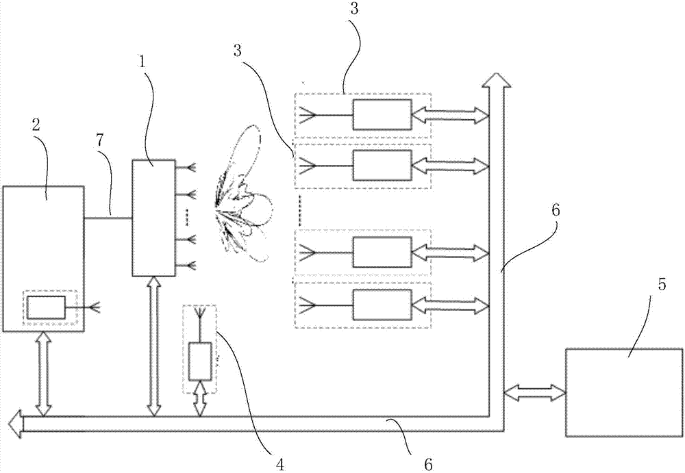
[0104] like Figure 4a As shown, in this embodiment, the digital test equipment 2 includes the second A / D circuit A / D2, the second DSP circuit DSP2 and the second D / A circuit D / A2 connected in sequence, and the second The A / D circuit A / D2, the second DSP circuit DSP2 and the second D / A circuit D / A2 are all connected to the data bus 6 respectively. like Figure 5a As shown, the digitized antenna probe 3 in this embodiment includes an uplink probe antenna 44, a fourth A / D circuit A / D4, a fourth DSP circuit DSP4, a fourth D / A circuit D / A4, and a downlink probe antenna connected in sequence 45, and the fourth A / D circuit A / D4, the fourth DSP circuit DSP4 and the fourth D / A circuit D / A4 are all connected to the data bus 6 respectively. The signal flow of this embodiment is:
[0105] In the uplink test working mode, the second DSP circuit DSP2 generates a digital signal under the control of the uplink state setting signal, and the second D / A circuit D / A2 is under the control of t...
Embodiment 2
[0108] like image 3 As shown, in order to make the digital antenna test system of the present invention applicable to a large-scale darkroom test environment, on the basis of Embodiment 1, the digital antenna test system also includes a digital receiver 4, which communicates with the The digitized antenna probe array and the digitized test equipment 2 are connected; the packaged data sent by the digitized antenna probe array in the uplink test mode of operation and the packaged data sent by the digitized test equipment 2 in the downlink test mode of operation After digital-to-analog conversion, a radio frequency signal is formed to radiate to the digital transmission receiver 4; the digital transmission receiver 4 is configured to sequentially perform low-noise amplification, sampling, analog-to-digital conversion, data processing and packaging of the received radiation signal , and send the packaged data to the central industrial computer 5 through the data bus. As a specif...
Embodiment 3
[0113] like Figure 4c As shown, in order to make the digital antenna test system provided by the present invention applicable in a high-frequency environment, as an optional implementation, the digital test equipment 2 further includes a first lower A frequency converter 21, a first up-converter 22 and a first frequency synthesizer 23, wherein the first down-converter 21 is connected to the second A / D circuit A / D2, and the first up-converter 22 is connected to the The second D / A circuit D / A2 is connected, the first frequency synthesizer 23 is connected between the first up-converter 22 and the first down-converter 21, and is connected to the data bus 6 and the second DSP circuit DSP2; wherein, the first down-converter 21 is configured to convert the frequency of the test signal sent by the antenna structure 1 to be tested from the first frequency range to the second frequency range, so as to For the second A / D circuit A / D2 to sample, for example, to convert the frequency of ...
PUM
 Abstract
Description
Claims
Application Information
 - R&D
- Intellectual Property
- Life Sciences
- Materials
- Tech Scout
- Unparalleled Data Quality
- Higher Quality Content
- 60% Fewer Hallucinations
Browse by: Latest US Patents, China's latest patents, Technical Efficacy Thesaurus, Application Domain, Technology Topic, Popular Technical Reports.
© 2025 PatSnap. All rights reserved.Legal|Privacy policy|Modern Slavery Act Transparency Statement|Sitemap|About US| Contact US: help@patsnap.com


