
Intelligent traffic light control method and system

A signal light control and traffic signal light technology, applied in the direction of controlling traffic signals, etc., can solve the problems of unachievable efficiency and accuracy, inconvenient maintenance and upgrade, poor scalability, etc., to avoid traffic accidents, good applicability and promotion. , the effect of reducing road congestion

Active Publication Date: 2017-07-21
SHENZHEN INST OF ADVANCED TECH CHINESE ACAD OF SCI
View PDF6 Cites 33 Cited by
  • Summary
  • Abstract
  • Description
  • Claims
  • Application Information

AI Technical Summary

Problems solved by technology

[0003] At present, the most widely used at home and abroad is magnetic frequency detection, that is, the vehicle detector is a loop coil, which is buried under the road surface to detect the traffic volume above the road, the road occupancy ratio and the speed of vehicles passing, but the laying of the equipment needs to be destroyed The ground is inconvenient to maintain and upgrade in the later stage, and the scalability is poor; the wave frequency detection is based on microwave, ultrasonic or infrared waves, etc., to detect the electromagnetic waves emitted by the vehicle, and the accuracy is acceptable, but the cost is high; with deep learning Wide application in the field of image recognition, image processing based on video detection, and vehicle recognition has become a hot spot in recent years, but has not yet been fully applied in practice
[0004] In short, the above traditional detection methods for vehicle identification and then control of traffic lights cannot achieve satisfactory results in terms of efficiency and accuracy.

Method used


Image

  • Intelligent traffic light control method and system
  • Intelligent traffic light control method and system
  • Intelligent traffic light control method and system

Examples


Embodiment Construction

[0022] The present invention will be described in further detail below in conjunction with the accompanying drawings and specific embodiments.

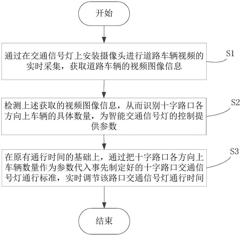
[0023] refer to figure 1 As shown, it is the operation flow chart of the preferred embodiment of the intelligent traffic signal light control method of the present invention.

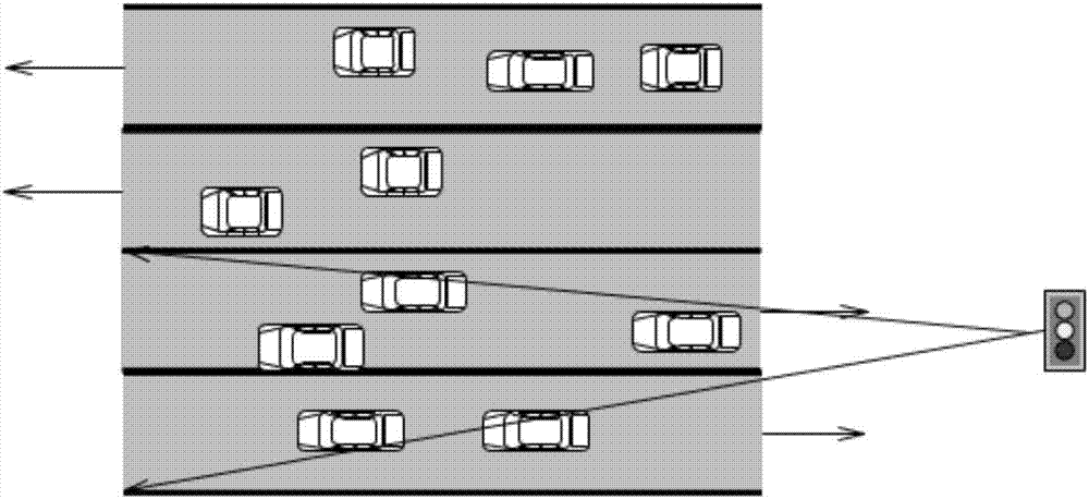
[0024] Step S1, by installing cameras on traffic lights for real-time collection of road vehicle video, the video image information of road vehicles is obtained, and the collection targets are roads and vehicles within a certain distance in the four directions of the intersection to provide analysis data for subsequent identification. in particular:

[0025] First, install cameras on traffic lights to configure video image information collection devices. In this embodiment, four traffic lights are respectively arranged at the crossroads, which are collected by a monitoring camera arranged on each traffic light. However, it is not ruled out that two traffic l...


PUM


Abstract

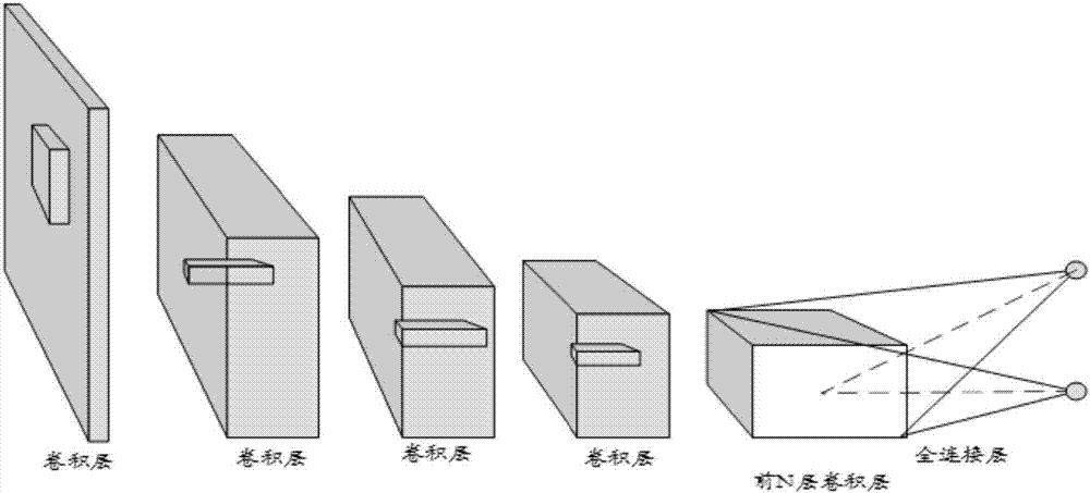
The invention relates to an intelligent traffic light control method. The method comprises: video image information of a road vehicle is obtained; pretreatment is carried out on the obtained video image information and a pre-training network model is constructed, a training network is built based on the pre-training network model, pre training is carried out on the built pre-training network, the training network is initialized by using pre-trained network parameters and the training network is trained by using a constructed data set until a vehicle number at a corresponding lane in a picture is detected in real time; and on the basis of original passing time, the detected vehicle number at the corresponding lane used as a parameter is substituted into a crossroad traffic light passing standard and the crossroad traffic light passing time is adjusted in real time. In addition, the invention also relates to an intelligent traffic light control system. According to the method and system provided by the invention, the green light passing time of the crossroad traffic light can be adjusted in real time based on vehicle recognition, so that road congestion can be reduced, the traffic accident can be avoided, and the passing efficiency can be enhanced.

Description

technical field [0001] The invention relates to an intelligent traffic signal lamp control method and system. Background technique [0002] The current traffic signal light control system attempts to control the traffic signal lights by identifying vehicles on the road in various ways. It is roughly divided into three types: magnetic frequency detection, wave frequency detection and video detection. The basic technologies relied on are different and each has its own advantages. [0003] At present, the most widely used at home and abroad is magnetic frequency detection, that is, the vehicle detector is a loop coil, which is buried under the road surface to detect the traffic volume above the road, the road occupancy ratio and the speed of vehicles passing, but the laying of the equipment needs to be destroyed The ground is inconvenient to maintain and upgrade in the later stage, and the scalability is poor; the wave frequency detection is based on microwave, ultrasonic or ...

Claims


Application Information

Patent Timeline
Patent Type & Authority Applications(China)
IPC IPC(8): G08G1/08
CPCG08G1/08
Inventor 王书强王永灿杨岳申妍燕胡明辉
Owner SHENZHEN INST OF ADVANCED TECH CHINESE ACAD OF SCI
Learn More