Calibration method and system for circuit board automatic test system

A technology of automatic test system and calibration method, which is applied to measuring devices, measuring electrical variables, instruments, etc., can solve problems such as time-consuming and labor-intensive, and achieve the effects of reducing manual operations, high positioning accuracy, and improving efficiency

Inactive Publication Date: 2017-07-25
深圳市赛伦北斗科技有限责任公司
View PDF4 Cites 8 Cited by
  • Summary
  • Abstract
  • Description
  • Claims
  • Application Information

AI Technical Summary

Problems solved by technology

If the initial position of the coordinate system is calibrated manually, it will be time-consuming and laborious

Method used


Image

  • Calibration method and system for circuit board automatic test system
  • Calibration method and system for circuit board automatic test system
  • Calibration method and system for circuit board automatic test system

Examples


Embodiment Construction

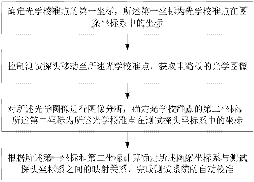
[0042] The present invention will be further described below in conjunction with the accompanying drawings and specific preferred embodiments, but the protection scope of the present invention is not limited thereby.

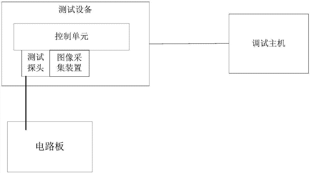
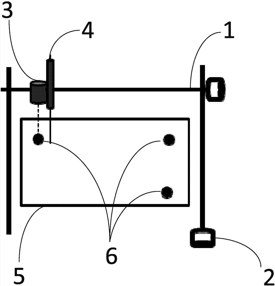
[0043] Such as image 3As shown, in the automatic test system of the circuit board, the schematic diagram of the PCB circuit board is stored in the host computer, and the pattern coordinate system (PQ coordinate system) of the schematic diagram of the PCB circuit board is determined in the host computer. In this embodiment, the pattern coordinate system is a plane Cartesian coordinate system, including a P axis and a Q axis, wherein the P axis is parallel to the horizontal direction of the PCB circuit board schematic diagram, and the Q axis is parallel to the vertical direction of the PCB circuit board schematic diagram , the origin of the pattern coordinate system is specified by the user in the host computer, generally the lower left corner of the schematic di...


PUM


Abstract

The invention discloses a calibration method and system for a circuit board automatic test system. The method comprises the following steps: S1, determining the first coordinate of an optical calibration point, wherein the first coordinate is the coordinate, of the optical calibration point, in a pattern coordinate system; S2, moving a test probe to the optical calibration point to acquire an optical image of a circuit board; S3, analyzing the optical image to determine the second coordinate of the optical calibration point, wherein the second coordinate is the coordinate, of the optical calibration point, in a test probe coordinate system; and S4, calculating a mapping relation between the pattern coordinate system and the test probe coordinate system based on the first coordinate and the second coordinate to complete the automatic calibration of the test system. The calibration method and system has automatic operation, high efficiency and high positioning precision.

Description

technical field [0001] The invention relates to the field of an automatic circuit board test system, in particular to a calibration method and system for a circuit board automatic test system. Background technique [0002] PCB board (Printed Circuit Board, printed circuit board) is one of the important components of the electronics industry. It can provide mechanical support for the fixing and assembly of various electronic components such as integrated circuits, realize the wiring and electrical connection or electrical insulation between various electronic components such as integrated circuits, and provide the required electrical characteristics, such as characteristic impedance, etc. Provide solder mask graphics for automatic soldering and provide identification characters and graphics for component insertion, inspection, and maintenance. Now almost every kind of electronic equipment, such as electronic watches, calculators, computers, communication electronic equipment...

Claims


Application Information

Patent Timeline
Patent Type & Authority Applications(China)
IPC IPC(8): G01R35/00
CPCG01R35/005
Inventor 扈啸陈胜刚罗诗途徐海军
Owner 深圳市赛伦北斗科技有限责任公司
Why Eureka
Try Eureka