Rechargeable particle catheter

A catheter and particle technology, used in balloon catheters, X-ray/γ-ray/particle irradiation therapy, therapeutic feeding tubes, etc. Less trauma, high application value, and guaranteed effect

Inactive Publication Date: 2017-07-28
牛洪欣
View PDF11 Cites 9 Cited by
  • Summary
  • Abstract
  • Description
  • Claims
  • Application Information

AI Technical Summary

Problems solved by technology

However, after the partial regression of the patient's tumor, the distance between the radioactive particles and the tumor on the wall of the tube increases, and they can no longer be in close contact with the tumor, which affects the therapeutic effect of the radioactive particles and fails to achieve the goal of highly conformal radiotherapy.

Method used


Image

  • Rechargeable particle catheter
  • Rechargeable particle catheter
  • Rechargeable particle catheter

Examples


Embodiment 1

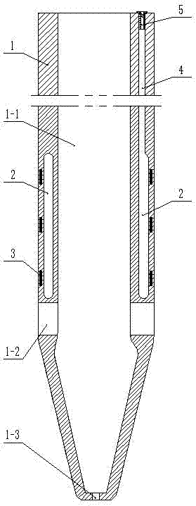
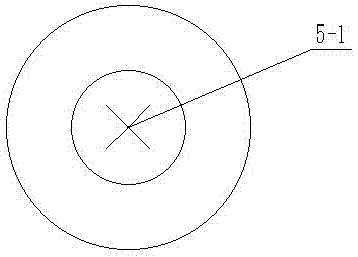
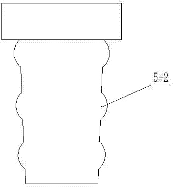
[0024] Such as figure 1 The shown inflatable particle catheter includes a catheter body 1, and the inside of the catheter body is a drainage cavity 1-1. The catheter body 1 is provided with a filling channel 4 and a capsule 2 surrounding the catheter body 1. The capsule is both It can be an inflatable bladder or a water-filled water bladder. One end of the filling channel 4 is provided with a valve body 5, and the other end of the filling channel 4 communicates with the bladder 2. On the bladder 2 Radioactive particles 3 are provided, and when the balloon expands, the expanded balloon will not squeeze the drainage cavity. Such as Figure 4 As shown, the particles 3 are pasted on the outer wall of the capsule body 2, and the capsule body 2 is also covered with an elastic sheath 6. When the capsule body 2 expands or contracts, the elastic sheath 6 expands or expands accordingly with the capsule body. Shrink, all the particles 3 are located in the elastic protective sheath 6. ...

Embodiment 2

[0029] Such as Figure 5 The main difference between the shown inflatable particle catheter and the first embodiment is that the particles 3 are stuck on the inner wall of the capsule body 2 .

Embodiment 3

[0031] Such as Image 6 Compared with the first embodiment, the shown inflatable particle catheter mainly differs in that the capsule body 2 is provided with a bag-type particle chamber 7, and the bag-type particle chamber 7 is an elastic module pasted on the surface of the capsule body 2. , the other edges on the elastic module except the upper edge are all bonded to the outer wall of the capsule body 2, the particles 3 are inserted into the bag-type particle warehouse 7, and the capsule body 2 is also provided with an elastic protective layer, all of the above The bag-type particle bins 7 are all located in the elastic protective layer, and the elastic protective layer prevents the capsule body 2 from affecting the particle 3 from falling out or shifting in the bag-type particle bin 7 when it expands.

[0032] Working principle: When using the particle catheter, before introducing it into the human body, avoid gas or liquid in the capsule body 2. After installing the radioac...


PUM


Abstract

The invention discloses a rechargeable particle catheter. The rechargeable particle catheter includes a catheter body, the catheter body is provided with a charge-in channel and a bag which surrounds the catheter body, one end of the charge-in channel is provided with a valve, the other end of the charge-in channel is communicated with the bag, the bag is provided with radioactive particles, and when the bag inflates, the inflated bag cannot extrude a drainage cavity. The rechargeable particle catheter can be widely used in obstructed or narrow cavities and tracts such as esophagi, stomach and intestines, bile ducts, nephric ducts and vena cave vessels in human bodies, and is wide in application prospect and high in application value. In the process of treating a patient, the catheter only needs to be introduced once, gas charging or liquid charging can be repeatedly conducted on the bag many times, after tumor treatment reaches an expected effect, gas discharging or liquid discharging can be conducted on the bag and then the particle catheter is taken out; multiple operations are not needed, the treatment process is simplified, treatment effects are ensured, the pain of patients is slight, wounds are small, and the rechargeable particle catheter is more acceptable to the patients.

Description

technical field [0001] The invention relates to an inflatable particle conduit. Background technique [0002] In previous clinical practice, for some patients with malignant cavity obstruction caused by tumors who lost the chance of surgery or were not suitable for surgical treatment, catheter placement was a commonly used clinical treatment method. Catheter placement only plays the role of nasal feeding or drainage to open up normal physiological channels, but it cannot play a role in treating tumors and cannot curb the continued development of tumors. [0003] Patent No. 2014103438569 discloses a medical particle catheter. The medical particle catheter includes a sleeve that is movably fitted on the catheter. The sleeve is provided with a radioactive particle fixation device used in tumor treatment. When in use, the particle fixation device is loaded Radioactive particles are introduced into the body with the catheter, and the catheter particle device is adjusted to the p...

Claims


Application Information

Patent Timeline
Patent Type & Authority Applications(China)
IPC IPC(8): A61M36/04A61M25/10A61J15/00A61M1/00
CPCA61M25/10A61N5/1002A61N5/1007A61N5/1014A61J15/0003A61N2005/1004A61N2005/1024A61M1/84
Inventor 牛洪欣张西坤徐忠法
Owner 牛洪欣
Why Eureka
Try Eureka