
Solid state spark device and exciter circuit using same

A solid-state, spark technology, applied in spark ignition controllers, other devices, jet propulsion devices, etc., can solve problems that affect the operation of the CDI system and exist risks

Active Publication Date: 2021-08-31
CHAMPION AEROSPACE INC
View PDF7 Cites 0 Cited by
  • Summary
  • Abstract
  • Description
  • Claims
  • Application Information

AI Technical Summary

Problems solved by technology

The use of glass SGTs filled with radioactive gas can present risks due to glass component breakage and gas leakage, thereby affecting CDI system operation

Method used


Image

  • Solid state spark device and exciter circuit using same
  • Solid state spark device and exciter circuit using same

Examples


Embodiment Construction

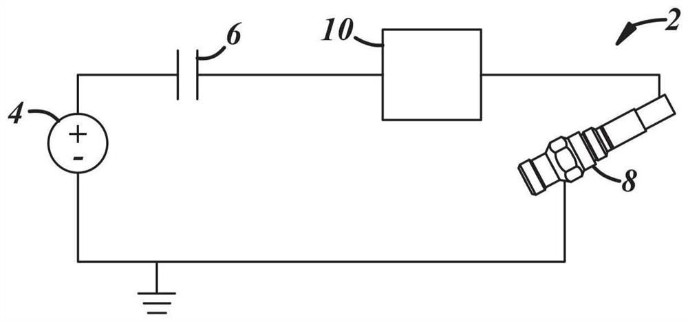
[0019] figure 1 A generalized block diagram is depicted showing an exemplary embodiment of a turbine engine ignition system 2 including a solid state device that provides sparking energy to an igniter without the need for a spark gap gas discharge tube (SGT). System 2 includes a power source 4 , a capacitive energy storage element 6 , an igniter 8 and a solid state spark device 10 . In general, the power source 4 may apply charge to a capacitive energy storage element, which may be a capacitor 6 as shown. When capacitor 6 accumulates sufficient charge, it causes igniter 8 to discharge, creating a spark that initiates combustion. Capacitor 6 and solid state spark device 10 together form an energizer, wherein spark device 10 operates as a switch that regulates the discharge of capacitor 6 across igniter 8 so as to allow discharge only when sufficient energy is present in capacitor 6 to thereby Make sure there is a strong enough spark.

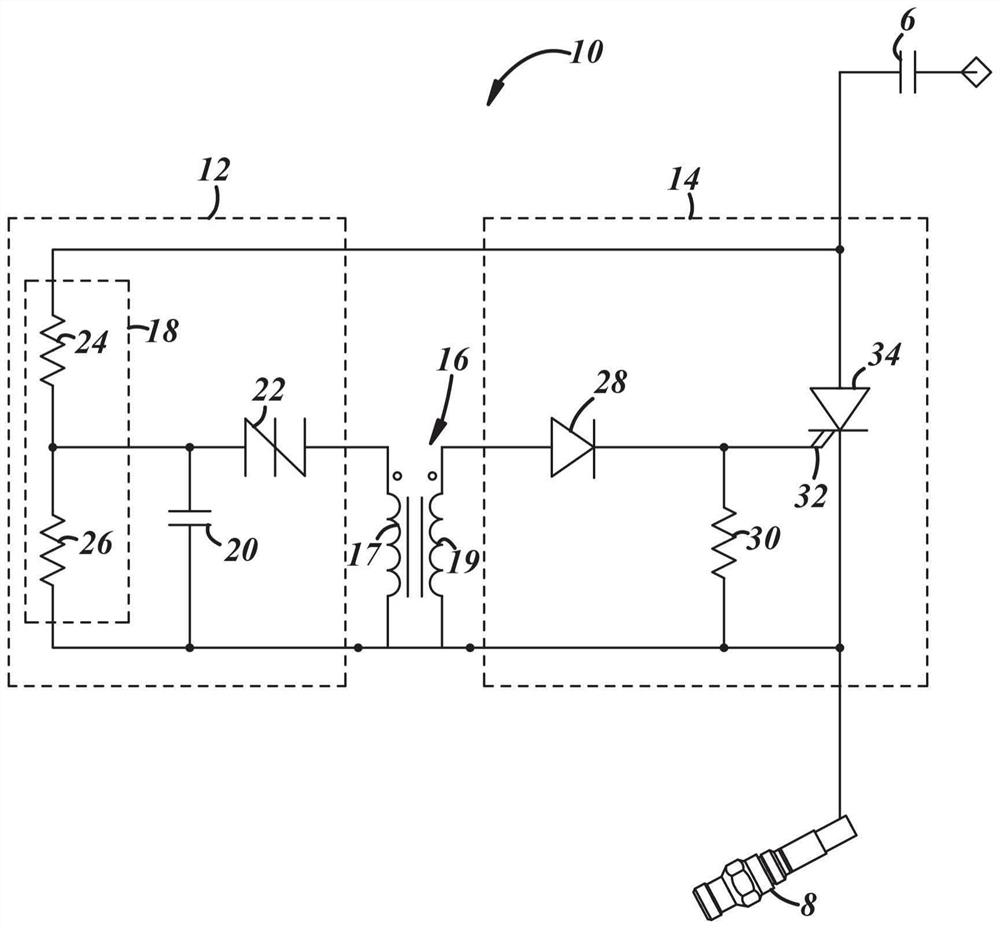
[0020] refer to figure 2 , a schemati...


PUM


Abstract

A solid-state spark device operating as a two-terminal spark gap in a CDI exciter for an aircraft ignition system. The device includes a trigger transformer, a trigger circuit and a control circuit. The trigger circuit is electrically connected to the first coil of the transformer and includes circuit elements connected to supply current to the first coil after the trigger circuit is charged to the trigger voltage. The induction of the current through the first coil of the trigger transformer in the second coil of the transformer induces an output. A control circuit is electrically connected to the second coil and includes a switch controlled by an output from the second coil. The switch discharges energy from the actuator into the igniter of the aircraft ignition system when activated by the trigger circuit.

Description

technical field [0001] The present invention relates generally to turbine engine ignition systems and, more particularly, to capacitive discharge ignition (CDI) actuators for use in aircraft jet engines. Background technique [0002] Airplanes are often powered by turbine engines. A turbine engine (also known as a gas turbine) is a type of internal combustion engine having an upstream rotary compressor coupled to a downstream turbine and a combustion chamber between them into which fuel is injected and combusted to produce a pressurized exhaust. As air enters the turbine engine, fuel is added and ignited using a suitable ignition system such as a capacitive discharge ignition (CDI) system. Capacitive discharge systems include an exciter that produces a spark discharge at an igniter in the combustion chamber to ignite the fuel. Typically, the exciter portion of a capacitive discharge ignition system uses a spark gap gas discharge tube (SGT) to generate this spark discharge...

Claims


Application Information

Patent Timeline
Patent Type & Authority Patents(China)
IPC IPC(8): F02C7/266
CPCF02C7/266F05D2260/99F05D2220/323F02P3/0807F02P15/003F05D2270/52
Inventor 史蒂夫·J·肯平斯基
Owner CHAMPION AEROSPACE INC
Learn More