
Improved type axial-flow compressor

An axial-flow compressor and an improved technology, applied in the field of compressors, can solve the problems that the axial-flow compressor cannot be miniaturized, increase the manufacturing cost of the axial-flow compressor, the difficulty of repair, and the space occupied, so as to reduce the difficulty of operation and maintenance and cost, improve cooling effect, reduce the effect of space occupied

Inactive Publication Date: 2017-07-28
曾戟
View PDF1 Cites 2 Cited by
  • Summary
  • Abstract
  • Description
  • Claims
  • Application Information

AI Technical Summary

Problems solved by technology

[0004] 1. Because the cold water pipeline needs to occupy a specific space in the body, the axial flow compressor of the same model and power cannot be miniaturized;
[0005] 2. The cold water pipeline needs to be made separately, and then installed in the axial flow compressor, which increases the production cost and repair difficulty of the axial flow compressor;

Method used


Image

  • Improved type axial-flow compressor
  • Improved type axial-flow compressor
  • Improved type axial-flow compressor

Examples


Embodiment 1

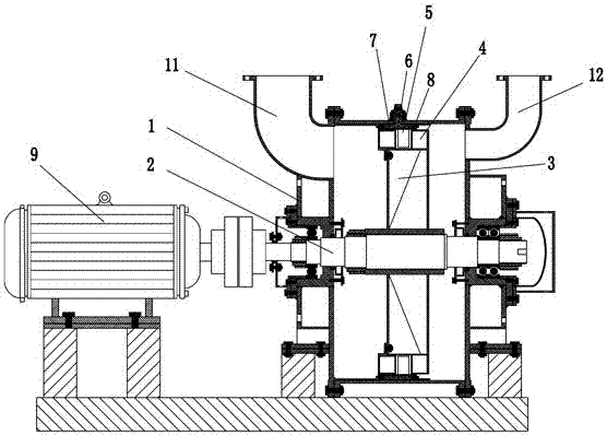
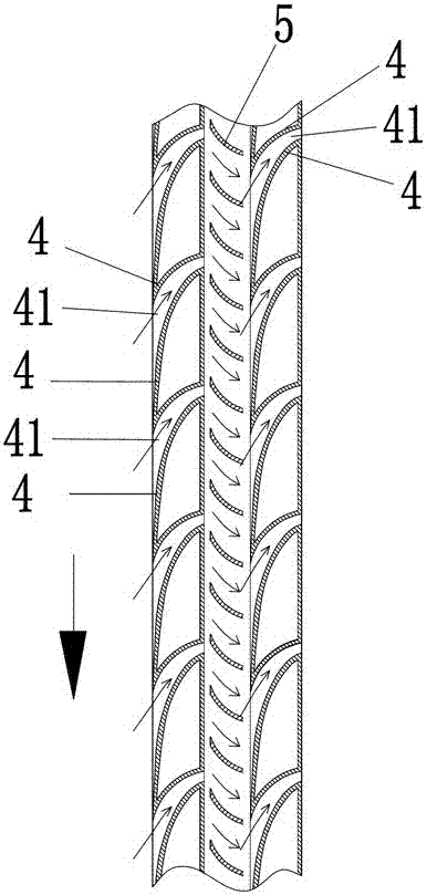
[0023] Such as Figure 1 to Figure 4 As shown, an improved axial flow compressor includes a body 1. The interior of the body 1 is hollow, and air inlets 11 and air outlets 12 are arranged on both ends. A rotating shaft 2 is arranged in the center of the body 1, and the rotating shaft 2 is connected to an external motor 9 to rotate. A runner 3 is fixed on the rotating shaft 2, and two sets of blades 4 that form an axial air flow when the runner 3 rotates are fixed on the circumferential surface of the runner 3. The two sets of blades 4 are arranged along the circumference of the runner 3 to form a 3 The front and rear groups on the circumferential surface form an air flow channel 41 between adjacent blades 4 on the same circle, and the inner wall of the body 1 between the two front and rear blades 4 is provided with a deflector 5 opposite to the direction of the blades 4 . Since the air flow passes through the two sets of blades 4 and the auxiliary blades 5 to form compressed ...

Embodiment 2

[0028] Another example Figure 5 Shown is another implementation of the invention. This realization scheme is an extension on the basis of the first embodiment, specifically adding three runners 3 parallel to the rotating shaft 2 , and a water cooling chamber 6 is provided between every adjacent blade 4 . The distribution and structure of blades 4 on each runner 3 and the distribution and structure of deflectors 5 are consistent with the structure and principle of Embodiment 1, and will not be repeated here.

[0029] After the air in this embodiment is compressed by the first stage, it is further compressed by the second stage and the third stage, so that the pressure of the gas is further increased and then increased, so that the compressed gas with higher pressure is output to meet the requirements of higher gas pressure. stressful occasions.

[0030] In addition to the above two schemes, four or more runners 3 can form more stages of compression units to provide higher-de...


PUM


Abstract

An improved axial flow compressor, including a machine body, air inlets and air outlets are respectively arranged at both ends of the machine body, a rotating shaft is arranged in the center of the body, a runner is fixed on the rotating shaft, and when the runner rotates, a Blades forming axial air flow, air flow passages are formed between adjacent blades, the blades are two groups of front and rear groups surrounding the circumferential surface of the runner, and the inner wall of the body between the two front and rear blades is provided with a direction opposite to the direction of the blades. The deflector is provided with a water cooling chamber for reducing the airflow temperature on the deflector fixed ring seat arranged between the two front and rear blades. The effect of the present invention is: changing the cold water pipeline into an annular water cooling chamber, reducing the space occupied by the original cold water pipeline, making the body structure of the axial flow compressor more concise and compact, and reducing the difficulty and cost of operation and maintenance. The airflow cooling space is effectively reduced, the contact surface between the airflow and the water cooling chamber is increased, the cooling effect of the airflow is improved, and the production cost is reduced.

Description

technical field [0001] The invention belongs to the technical field of compressors, and in particular relates to an improved axial flow compressor. Background technique [0002] An air compressor is a general-purpose device that produces high-pressure gas and has a wide range of applications. Among the existing air compressors, there are generally two types of reciprocating (piston type) and screw type air compressors, and other types are smaller. Both reciprocating and screw air compressors are volumetric principle structures, both of which have friction and are inseparable from the lubrication of oil. Therefore, the ensuing failure rate is high, energy consumption is large, the volume is large, the cost is high, and the discharge The gas contains oil. For some users who have special requirements to discharge gas without oil, they can only consider choosing centrifugal air compressors, but centrifugal compressors are expensive, and the quality of domestic centrifugal air c...

Claims


Application Information

Patent Timeline
Patent Type & Authority Applications(China)
IPC IPC(8): F04D25/08F04D29/58F04D29/54F04D19/02F04D29/32
CPCF04D25/08F04D19/028F04D29/321F04D29/541F04D29/5826
Inventor 曾戟
Owner 曾戟
Learn More