
Monitorable street lamp

A technology of street lamps and light poles, applied in the field of lighting, can solve the problems of messy city appearance, time-consuming, labor-intensive, and impact, and achieve the effects of preventing targeted damage, increasing the scope of monitoring, and facilitating extraction

Pending Publication Date: 2017-07-28
钱建冲
View PDF4 Cites 6 Cited by
  • Summary
  • Abstract
  • Description
  • Claims
  • Application Information

AI Technical Summary

Problems solved by technology

However, the installation of the monitoring system requires the laying of new lines and support poles, which is not only time-consuming and labor-intensive, but also has a messy impact on the appearance of the city due to the everywhere camera support poles.

Method used


Image

  • Monitorable street lamp

Examples


Embodiment 1

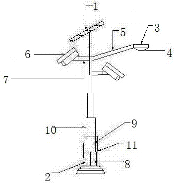
[0016] Embodiment 1: see figure 1 , a monitorable street lamp, the monitorable street lamp includes a power generation component, a lighting component, a monitoring component and a support component; the power generation component is located inside and at the upper end of the support component; The components are fixed on the outer wall of the support component; the support component is fixed on the ground. The design structure is simple and clear, and the components are closely connected without mutual influence, which not only has a long service life but also facilitates production and installation. The power generation assembly includes a photovoltaic panel 1 and a battery pack 2, and the photovoltaic panel is fixed on the top of a hydraulic telescopic light pole; the battery pack 2 is installed in a street lamp base. Photovoltaic panels generate electrical energy during the day and store it in the battery pack. At night or in rainy weather, the electrical energy is releas...

Embodiment 2

[0017] Example 2: see figure 1 , as an improvement of the present invention, the wireless router 8 connects the pictures collected by the FCS9 to the Internet through mobile data signals. By integrating the wireless router into the Internet, the pictures taken by the movable camera can be transmitted to the remote monitoring terminal in real time, and can be connected with handheld police office systems such as Jingwutong. Grassroots law enforcement officers can view real-time pictures anytime, anywhere, or Play back the recorded video in reverse gear.

Embodiment 3

[0018] Embodiment 3: see figure 1 , as an improvement of the present invention, the movable camera is connected to the wireless router through a WIFI signal, and the camera angle of the movable camera can be regulated through an Internet terminal, thereby reducing the occurrence of dead angles in the camera and increasing the monitoring range, The movable camera 6 is provided with a large-capacity hard disk inside. The images recorded by the camera will be backed up in the hard disk. When the device cannot connect to the Internet, the hard disk can be removed and the required screen can be directly retrieved from the hard disk.


PUM


Abstract

The invention relates to a monitorable street lamp. The monitorable street lamp is characterized by comprising an electricity generating assembly, a lighting assembly, a monitoring assembly and a supporting assembly; the electricity generating assembly is positioned in the supporting assembly and at the upper end of the supporting assembly; the lighting assembly is arranged at the top end of one side of the supporting assembly; the monitoring assembly is fixed on the outer wall of the supporting assembly; the supporting assembly is fixed on the ground; the electricity generating assembly comprises a photovoltaic panel and storage batteries; the photovoltaic panel is fixed at the top end of a hydraulic telescopic lamp post; and the storage battery group is arranged in a street lamp pedestal. The whole technical scheme is compact in structure, low in cost, energy-saving and environmentally-friendly. According to the technical scheme, the monitoring equipment is added on the basis of the design of the original traditional lighting street lamp, so the monitorable street lamp has the night lighting function and also has the functions of monitoring in real time, recording and saving. The monitorable street lamp can be conveniently added into an urban road monitoring network or a safety monitoring network, so the cost required by installation of an urban monitoring system is greatly saved.

Description

technical field [0001] The invention relates to a monitorable street lamp, which belongs to the technical field of lighting. Background technique [0002] Street lamps are a commonly used roadside lighting tool. It is ubiquitous and indispensable in modern cities. The appearance of street lights not only brings light and convenience to people's nighttime appearance, but also is an indispensable part of beautifying the city's night scene. With the progress of the society and the development of the economy, in order to deal with various increasingly complex public security issues, traffic issues and environmental protection issues, the country has begun to vigorously develop the Skynet monitoring system. By installing large-density, high-definition cameras, the The corner is monitored around the clock without dead ends. And strive to eliminate illegal and criminal acts in the bud, and bring great deterrence to criminals. However, the installation of the monitoring system r...

Claims


Application Information

Patent Timeline
IPC IPC(8): F21S9/03F21V33/00F21V21/108F21V21/22F21V21/02H04N5/225H04N7/18F21V3/00F21Y115/10F21W131/103
CPCH04N7/18F21S9/035F21V3/00F21V21/02F21V21/108F21V21/22F21V33/0052F21W2131/103H04N23/00Y02B20/72
Inventor 钱建冲
Owner 钱建冲
Learn More