Fault detection circuit of relay and relay with the same

A relay failure and circuit detection technology, applied in circuit breaker testing, instrumentation, measuring electricity, etc., can solve problems such as delay in circuit fault detection, unfavorable control system maintenance, lack of self-detection on-off status and fault status, etc. The effect of reducing various losses and improving detection efficiency

Pending Publication Date: 2017-07-28
ZHEJIANG YINGLUOHUA NEW ENERGY TECH CO LTD
View PDF7 Cites 13 Cited by
  • Summary
  • Abstract
  • Description
  • Claims
  • Application Information

AI Technical Summary

Problems solved by technology

[0003] The present invention solves the defect that the existing relay does not have the self-detection on-off state and fault state, which leads to the occurrence of circuit faults easily, and when the control circuit fails, the location of the fault point cannot be quickly and accurately judged. , which brings delays to circuit fault detection and is not condu

Method used


Image

  • Fault detection circuit of relay and relay with the same
  • Fault detection circuit of relay and relay with the same
  • Fault detection circuit of relay and relay with the same

Examples


Embodiment 1

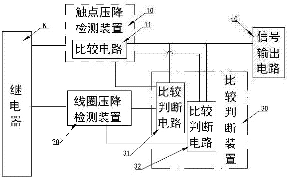
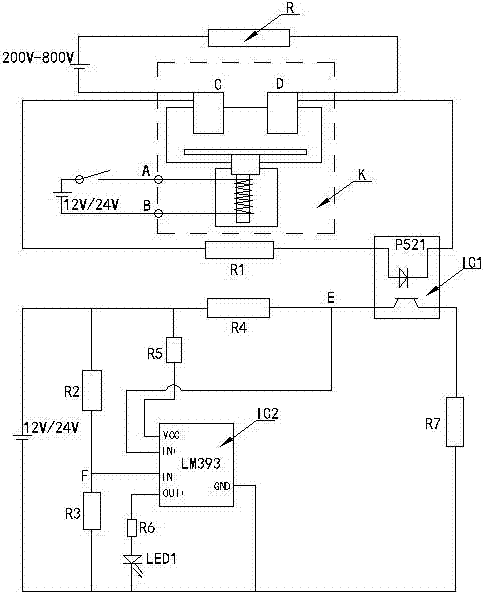
[0022] figure 1 , figure 2 In the illustrated embodiment, a relay failure detection circuit includes a contact voltage drop detection device 10 and a signal output circuit 40. The contact voltage drop detection device 10 detects the voltage drop across the relay contact CD, and the contact voltage drop detection When the device 10 detects and judges that there is a fault state at both ends of the relay contact CD, the signal output circuit outputs a fault signal 40 to indicate that the relay is in a fault or failure state; the contact voltage drop detection device includes a comparison circuit 11 and an optical coupler IC1, optically coupled The IC detects the contact voltage drop signal at both ends of the relay contact. When the voltage drop at both ends of the relay contact is detected, the relay contact is in the open state; the output terminal of the optocoupler IC1 inputs the contact to the comparator circuit 11 Voltage drop signal: After the contact voltage drop detectio...

Embodiment 2

[0024] figure 1 , image 3 In the illustrated embodiment, it also includes a coil voltage drop detection device 10 that detects electrical signals at both ends of the relay coil and a comparison judgment device 30 that compares and judges that the relay is in a normal or failed state. The contact voltage drop detection device is provided with There is a comparison circuit 10 and a signal output circuit 40. The comparison circuit is equipped with a voltage comparator and an optocoupler IC1. The comparison circuit detects the on-off state of the relay contact CD, and converts the on-off state into a contact voltage drop signal input for comparison Voltage comparison terminal in the circuit; detect the contact voltage drop at both ends of the relay contact through the optocoupler IC1. When the voltage drop at both ends of the relay contact is detected, the relay contact is in the disconnected state, and the signal output circuit outputs a prompt The comparison and judgment device 3...

Embodiment 3

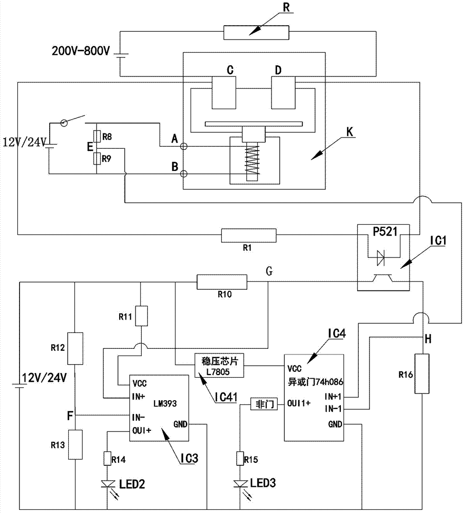
[0026] figure 1 , Figure 4 The illustrated embodiment further includes a coil signal detection device 20 for detecting voltage drop signals at both ends of the coil of the relay, and a comparison judgment device 30 for comparing and judging whether the relay is in a normal or failed state, and the contact voltage drop detection device 10 The contact voltage drop signal at both ends of the relay contact is detected, and the coil signal detection device 20 detects and obtains the coil voltage drop signal at both ends of the relay coil. The contact voltage drop signal and the coil voltage drop signal are input and compared to the judgment comparison circuit of the judgment device 30 In 32, the comparison and judgment device compares and judges whether the relay is in a normal or failed state, and detects whether the relay is in a normal or failed state through the signal output circuit. The judgment comparison circuit 32 in the comparison judgment device 30 includes a second volt...


PUM


Abstract

The invention discloses a fault detection circuit of a relay and a relay with the same. The fault detection circuit comprises a contact voltage drop detection device and a signal output circuit. The contact voltage drop detection device detects voltage drops of two ends of a contact of the relay. When it is judged that two ends of the contact of the relay are in a fault state, the signal output circuit outputs fault signals to prompt that it is judged that the relay breaks down or fails. The contact voltage drop detection device comprises a comparison circuit and an optical coupler. The optical coupler detects to obtain contact voltage drop signals of two ends of the contact of the relay. When detecting that two ends of the contact of the relay have voltage drops, it shows that the contact of the relay is in a disconnected state. The output end of the optical coupler inputs a contact voltage drop signal to the comparison circuit. After the contact voltage drop detection device acquires the contact voltage drop signal, the contact voltage drop detection device outputs the acquired fault judgment signal through detection to a signal output circuit to judge and prompt that the relay is in a fault or failure state. Thus, the position where the system fault point is located can be quickly judged, the fault detection efficiency is high and fault loss is low.

Description

Technical field [0001] The invention relates to a relay, in particular to a relay for detecting the fault state of the relay contact. Background technique [0002] A relay is a commonly used electrical control device. It is an electrical appliance that causes the controlled quantity to undergo a predetermined step change in the electrical output circuit when the input excitation quantity changes to the specified requirements. It has an interactive relationship between the control system or input loop and the controlled system or output loop. Usually used in automated control circuits, relays are often used in actual circuits as a kind of "automatic switch" to control large current operation through small currents, and are widely used in many occasions, playing automatic adjustment and safety in the circuit Protection, conversion circuit, etc. Since the relay is an automatic switching element with isolation function, it is widely used in remote control, telemetry, communication,...

Claims


Application Information

Patent Timeline
IPC IPC(8): G01R31/327
CPCG01R31/3278Y04S10/52
Inventor 宋文荣于荣爱张统杜德进
Owner ZHEJIANG YINGLUOHUA NEW ENERGY TECH CO LTD
Why Eureka
Try Eureka