Connector housing heat radiation structure

A heat dissipation structure and connector technology, which is applied in the direction of instrumentation, electrical equipment structural parts, cooling/ventilation/heating transformation, etc., can solve the problems of reduced EMI shielding effect, easy to be damaged by external force, weak buckle strength, etc., to achieve Increase the effective heat dissipation area, not easy to loose, improve the effect of strength

Active Publication Date: 2017-07-28
NEXTRONICS ENG CORP
View PDF5 Cites 22 Cited by
  • Summary
  • Abstract
  • Description
  • Claims
  • Application Information

AI Technical Summary

Problems solved by technology

However, conventional heat sinks must be fastened to the openings of the housing with fasteners, and the setting of the openings will reduce the EMI shielding effect.
Furthermore, conventionally known fasteners that are fastened front and rear are relatively weak in strength, and are easily damaged by external forces and are easy to loosen.

Method used


Image

  • Connector housing heat radiation structure
  • Connector housing heat radiation structure
  • Connector housing heat radiation structure

Examples


no. 1 example

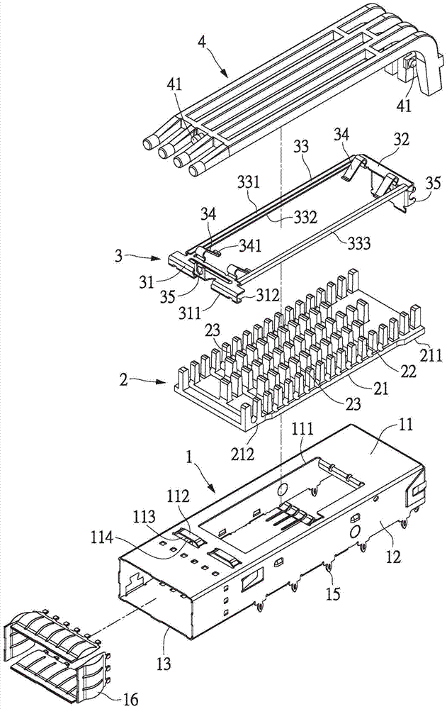
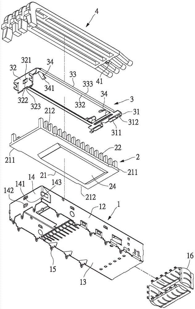
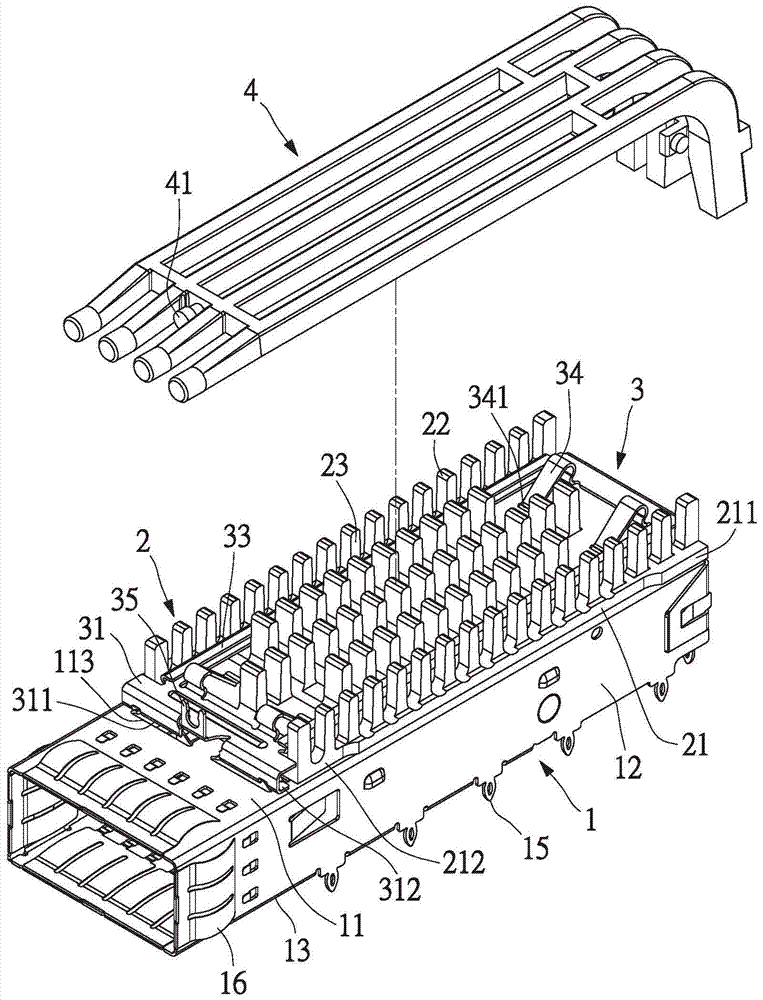
[0028] see figure 1 and figure 2 , the present invention provides a connector shell heat dissipation structure, which meets the requirements of the small pluggable connector specification, not only applicable to the structure of 1×1 specification, but also can be used in left and right side-by-side designs, such as 1×2~1× 6 gauge structure. The heat dissipation structure of the connector housing includes a housing 1, a heat sink 2 and a buckle 3. The housing 1 is provided with one, and its width can be changed corresponding to different specifications such as 1×1˜1×6. There are one, two, three, four, five or six cooling fins 2 and holding parts 3 corresponding to different specifications such as 1×1˜1×6. This embodiment discloses a structure with a size of 1×1, and there is one housing 1 , one cooling fin 2 and one holding member 3 .

[0029] The shell 1 is a metal shell, and the shell 1 includes a top plate 11 , two side walls 12 , a bottom plate 13 and a rear cover 14 . ...

no. 2 example

[0041] see Figure 8 and Figure 9 , the housing 1 can be provided with at least one middle partition 17, the middle partition 17 and the two side walls 12 are parallel to each other, in order to divide the inside of the housing 1 into at least two spaces, the heat sink 2 and the At least two fasteners 3 are provided corresponding to the at least two spaces. This embodiment discloses a structure with a 1×4 specification. The casing 1 is provided with one. The width of the casing 1 is increased, and its width is roughly four times that of the 1×1 specification. The heat sink 2 and the buckle 3 There are four correspondingly. In this embodiment, there are three intermediate partitions 17 , which divide the interior of the housing 1 into four spaces. The number of the middle partitions 17 can also be changed according to different specifications of the connectors, for example, one or two, or four or five, etc. can be provided. The through hole 111, buckle piece 112, opening 1...


PUM


Abstract

A connector housing heat radiation structure comprises a housing, a heat radiating plate and a buckling member. The first end of the buckling member is buckled and fixed with the top plate of the housing by means of a first tongue plate and a buckling plate, thereby reducing area of an opening on the top plate, and realizing relatively high EMI shielding effect. Two connecting arms of the buckling member penetrate through grooves in the heat radiating plate. Width of the heat radiation plate is not limited, and heat radiation area of the heat radiating plate can be increased. The second end of the buckling member is provided with a second tongue plate which is inserted into a bump at the back cover of the housing. Furthermore through making the abutting end of the second end abut against a backstop part, no easy loosening of the buckling member is realized. The buckling cannot be damaged in bearing pressing by a certain external force.

Description

technical field [0001] The present invention is to provide a heat dissipation structure of a connector housing, especially a heat dissipation structure of a connector housing applied to a small pluggable module. Background technique [0002] Conventional transceiver modules are usually used to connect circuit boards of communication lines and other electrical modules or devices. Different industry standards define connector types for different interfaces between computers and external communication devices such as modems, network interfaces, or other transceiver modules. The well-known GBIC (Gigabit Interface Converter) is a transceiver module for a computer to communicate with Ethernet, Fiber Channel or other data communication environments. [0003] In order to increase the port density when interconnecting with network devices (such as switches, cable patch panels, distribution boxes, computer output / input ports, etc.), it is generally desired to miniaturize the transcei...

Claims


Application Information

Patent Timeline
Patent Type & Authority Applications(China)
IPC IPC(8): G02B6/42H05K7/20
CPCG02B6/4256G02B6/4269H05K7/20409
Inventor 苏侯安曾定勇
Owner NEXTRONICS ENG CORP
Why Eureka
Try Eureka