
Power-adjustable backward wave oscillator

An oscillator and return wave technology, applied in the field of microwave electric vacuum, can solve the problems of large volume, unfavorable miniaturization and integration of the return wave tube, and achieve the effects of high electronic efficiency, reduced magnetic field response, and high power output.

Inactive Publication Date: 2017-07-28
UNIV OF ELECTRONICS SCI & TECH OF CHINA
View PDF7 Cites 18 Cited by
  • Summary
  • Abstract
  • Description
  • Claims
  • Application Information

AI Technical Summary

Problems solved by technology

However, the return wave tube is generally bulky, which is not conducive to miniaturization and integration. There is an urgent need for a new type of return wave tube with small size, high power, and easy integration to realize power adjustment to improve the flexibility of electromagnetic energy equipment and reduce power consumption. consumption

Method used

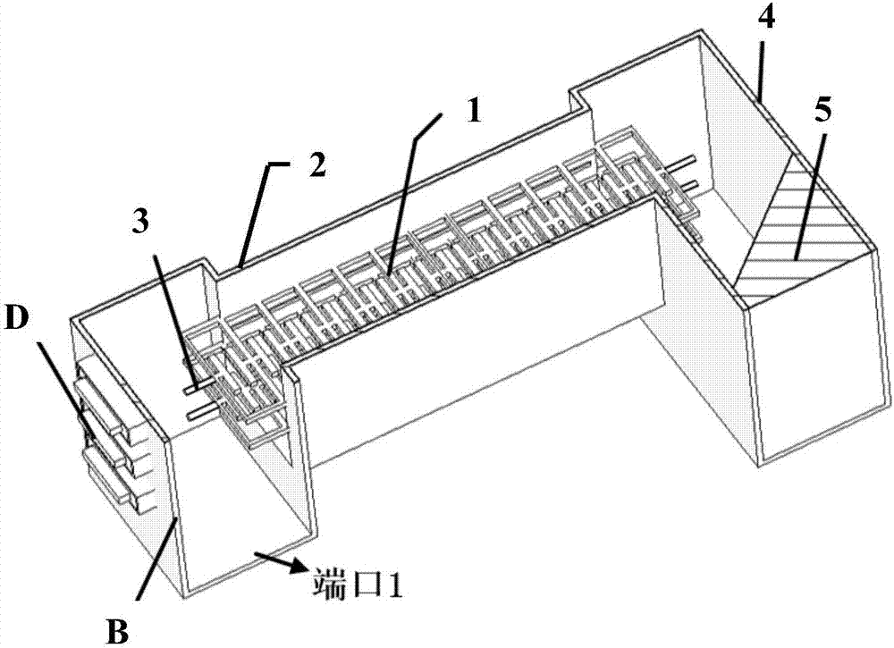
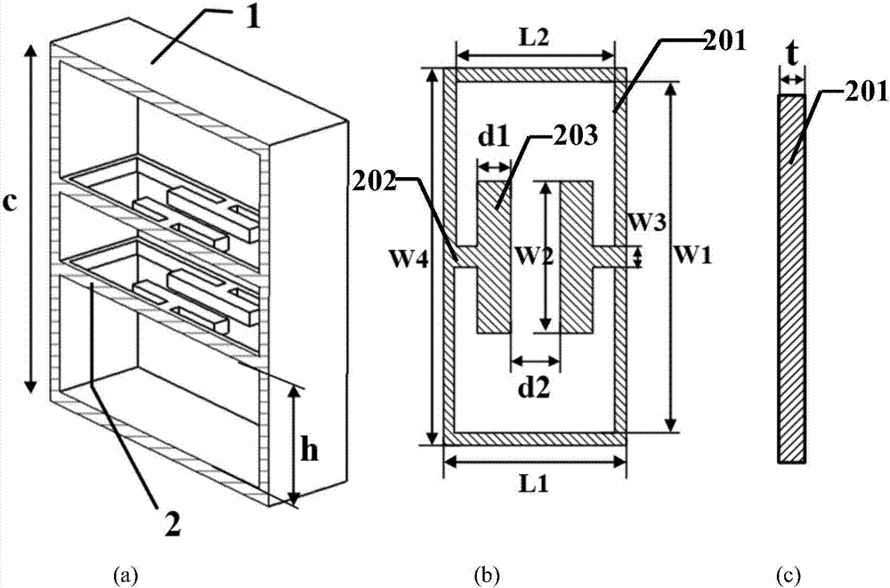

Image

  • Power-adjustable backward wave oscillator
  • Power-adjustable backward wave oscillator
  • Power-adjustable backward wave oscillator

Examples


Embodiment Construction

[0032] Specific embodiments of the present invention will be described below in conjunction with the accompanying drawings, so that those skilled in the art can better understand the present invention. It should be noted that in the following description, when detailed descriptions of known functions and designs may dilute the main content of the present invention, these descriptions will be omitted here.

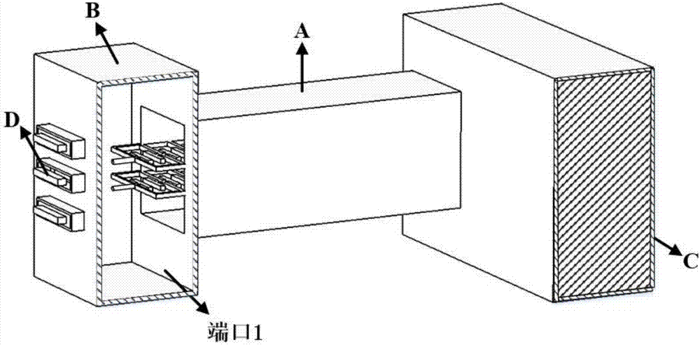
[0033] figure 1 It is a structural schematic diagram of a specific embodiment of the power-adjustable return wave oscillator of the present invention.

[0034] In this example, if figure 1 As shown, the power-adjustable return wave oscillator of the present invention includes a slow wave structure A, an output coupling structure B, a terminal matcher C and an emitting cathode D. The input end of the slow wave structure A is connected to the output coupling structure B, and the output end is connected to the terminal matcher C. The output coupling structure B is an output...


PUM


Abstract

The invention discloses a power-adjustable backward wave oscillator. The power-adjustable backward wave oscillator is characterized in that: by inserting upper and lower two rows of periodically complementary split-ring resonator structure into the middle part of a cavity of rectangular waveguide vertically, the complementary split-ring resonator structure has a relatively higher electric field resonant response at the slit of the opening, that is, between the horizontal branches of the two half parts, and shows the meta-material electromagnetic characteristic with a negative dielectric constant epsilon and a negative magnetic permeability Mu; longitudinal resonant field intensity is formed at the upper surface and lower surface of the periodically complementary split-ring resonator structure, thus being conductive to interaction between charged particles of band-shaped electron beams and electromagnetic waves; and at the same time, three electron beam channels are formed. Therefore, compared with a traditional relativism backward wave oscillator, the power-adjustable backward wave oscillator has higher coupling impedance and can obtain very high power output and electron efficiency. Besides, the structure enables one electron beam to work individually, or enables two electron beams or three electron beams to work, so that three kinds of adjustable power output of single beam, double beam and three-beam can be formed and then multi-band-shaped power can be adjustable.

Description

technical field [0001] The invention belongs to the field of microwave electric vacuum technology, and more specifically relates to a power-adjustable return wave oscillator. Background technique [0002] Since microwave electron tubes began to come into people's sight in the 1930s, microwave vacuum devices have played an irreplaceable role in both modern military confrontation and national economic construction. For a long period of time, microwave electric vacuum tubes have received extensive attention and achieved rapid development. However, the rapid rise of semiconductor solid-state devices has brought great impact and challenges to microwave electric vacuum devices. [0003] The application of microwave electric vacuum devices is mainly in high frequency and high power, while the application of semiconductor solid state devices is mostly in low frequency and low power. When the frequency of semiconductor solid-state devices is about 1GHz, its average power is about 10...

Claims


Application Information

Patent Timeline
Patent Type & Authority Applications(China)
IPC IPC(8): H01J25/46H01J23/24
CPCH01J23/24H01J25/46H01J2223/24H01J2225/46
Inventor 吴钢雄魏彦玉雷霞丁冲李倩岳玲娜宫玉彬
Owner UNIV OF ELECTRONICS SCI & TECH OF CHINA
Learn More