Microfluidic integration device with adjustable and controllable throughput and manufacturing method thereof

An integrated device and microfluidic technology, which is applied in chemical instruments and methods, laboratory containers, laboratory utensils, etc., can solve the problems that a single chip cannot be processed, the processing throughput of the chip is small, and the product is not perfect. Achieve the effect of low chip production cost, simple structure and high speed

Inactive Publication Date: 2017-08-01
SOUTHEAST UNIV
View PDF6 Cites 20 Cited by
  • Summary
  • Abstract
  • Description
  • Claims
  • Application Information

AI Technical Summary

Problems solved by technology

[0003] However, domestic microfluidic products are just in their infancy, the technology is not mature enough, and the products are not perfect enough
In order to achieve higher control accuracy, the size of microfluidic flow channels is generally tens to hundreds of microns, and due to the limitation of volume, the processing throughput of a single chip is small, the cost problem caused by high processing accuracy and low throughput The resulting processing speed has become a bottleneck in the commercialization of microfluidic chips
At the same time, due to the different volumes of samples, the required flow will be different, and a single chip obviously cannot handle various large sample volumes.

Method used


Image

  • Microfluidic integration device with adjustable and controllable throughput and manufacturing method thereof
  • Microfluidic integration device with adjustable and controllable throughput and manufacturing method thereof
  • Microfluidic integration device with adjustable and controllable throughput and manufacturing method thereof

Examples


Embodiment Construction

[0027] Below in conjunction with accompanying drawing and specific embodiment the present invention is described in further detail:

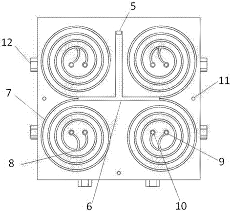
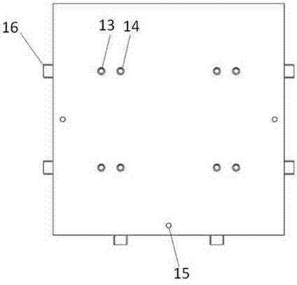
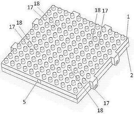
[0028] The invention provides a microfluidic device based on a Lego model with adjustable processing flux and a high-throughput concentration of micron-sized particles and a manufacturing method thereof, which is achieved by using a plurality of Lego modules to stack vertically and concentrating samples at the same time. High-throughput processing requirements and the purpose of free regulation of processing flux.

[0029] The flow distribution module and the bottom current collection module of this embodiment are manufactured using translucent resin as a raw material by 3D printing technology. Due to the narrow spiral flow channel of the functional module, the direct printing accuracy may not be enough, and it is easy to be deformed and blocked, so it needs to be realized by micro-machining technology. The main body of the microfluidic chip in...


PUM


Abstract

The invention relates to a micrometer-level particle high-throughput concentration microfluidic device with adjustable and controllable treatment throughput. The microfluidic device comprises three modules; a fluid separating module is used for uniformly distributing samples into function modules according to the flow rate requirement; each layer of function module is formed by bonding an upper template and a lower template, the sample flows into the corresponding modules via an entrance of each layer and is treated by a spiral flow channel, and target liquid and waste liquid are respectively guided out of two exits; the whole device can realize the vertical stacking of the multiple function modules via the upper and lower bonding mechanism of a Lego model, and the target liquid and waste liquid outlets of each layer are respectively positioned on convex cylinders of the Lego, and are vertically communicated; under the lowermost layer of function module, a bottom fluid collecting module is stacked, and the target liquid and the waste liquid are respectively gathered and then flow out. The microfluidic device has the advantages that by adopting the mcirofluid channel structure, the samples with different treatment throughputs can be quickly concentrated by the Lego module with adjustable layer number, the concept of fixed treatment throughput in the single microfluidic chip is broken through, and the effect of high throughput and continuous fluid concentration of micrometer-level biological particles is realized by the microfluid inertial effect.

Description

technical field [0001] The invention relates to the field of microfluidic integrated devices, in particular to a Lego model-based microfluidic device with adjustable flux and high-flux concentration of micron-sized particles and a manufacturing method thereof. Background technique [0002] Microfluidic chip technology integrates the basic operation units such as sample preparation, reaction, separation, and detection in the process of biological, chemical, and medical analysis into a micron-scale chip to automatically complete the entire analysis process. It has many advantages: the required sample solution is small, the analysis efficiency is high, and it is easy to package, etc. It can analyze multiple samples at the same time, and it only takes a few minutes or even a few seconds to automatically realize the sample collection, reaction, filtration, Basic processes such as sorting and testing. Particle separation technology has been widely used in the fields of medical di...

Claims


Application Information

Patent Timeline
Patent Type & Authority Applications(China)
IPC IPC(8): B01L3/00
CPCB01L3/502707B01L3/502715B01L2300/0848B01L2300/0861B01L2300/0887
Inventor 刘家铭
Owner SOUTHEAST UNIV
Why Eureka
Try Eureka