Grinding abrasion wheel for transmission shaft
A transmission shaft and grinding wheel technology, applied in the field of grinding, can solve the problems of easy breakage, small hardness of grinding wheel, poor wear resistance, etc., and achieve the effect of small grinding force, high grinding efficiency and long service life
- Summary
- Abstract
- Description
- Claims
- Application Information
AI Technical Summary
Problems solved by technology
Method used
Image
Examples
Embodiment 1
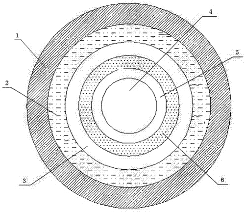
[0013] A grinding wheel for transmission shafts, comprising a grinding wheel body and a through hole 4 arranged at the center of the grinding wheel body, the outermost end of the grinding wheel body is provided with a grinding layer, and the grinding layer includes a first grinding layer 1, The second grinding layer 2, an installation layer 5, a glass fiber reinforced mesh 6 and an annular resin support disc 3 are sequentially arranged between the through hole 4 and the second grinding layer 2, and the installation layer 5 is made of polypropylene composite It is made of ethylene-propylene rubber, and the included angle between the surface of the annular resin support disc 3 and the plane where the through hole 4 and the installation layer 5 are located is: 1°-15°. As a preferred solution, the annular resin support disc 3 of the present invention and The included angle between the through hole 4 and the plane where the mounting layer 5 is located is: 10°; the raw material compo...
Embodiment 2
[0015] A grinding wheel for transmission shafts, comprising a grinding wheel body and a through hole 4 arranged at the center of the grinding wheel body, the outermost end of the grinding wheel body is provided with a grinding layer, and the grinding layer includes a first grinding layer 1, The second grinding layer 2, an installation layer 5, a glass fiber reinforced mesh 6 and an annular resin support disc 3 are sequentially arranged between the through hole 4 and the second grinding layer 2, and the installation layer 5 is made of polypropylene composite It is made of ethylene-propylene rubber, and the included angle between the surface of the annular resin support disc 3 and the plane where the through hole 4 and the installation layer 5 are located is: 1°-15°. As a preferred solution, the annular resin support disc 3 of the present invention and The included angle between the through hole 4 and the plane where the mounting layer 5 is located is: 10°; the raw material compo...
Embodiment 3
[0017] A grinding wheel for transmission shafts, comprising a grinding wheel body and a through hole 4 arranged at the center of the grinding wheel body, the outermost end of the grinding wheel body is provided with a grinding layer, and the grinding layer includes a first grinding layer 1, The second grinding layer 2, an installation layer 5, a glass fiber reinforced mesh 6 and an annular resin support disc 3 are sequentially arranged between the through hole 4 and the second grinding layer 2, and the installation layer 5 is made of polypropylene composite It is made of ethylene-propylene rubber, and the included angle between the surface of the annular resin support disc 3 and the plane where the through hole 4 and the installation layer 5 are located is: 1°-15°. As a preferred solution, the annular resin support disc 3 of the present invention and The included angle between the through hole 4 and the plane where the mounting layer 5 is located is: 10°; the raw material compo...
PUM
 Abstract
Description
Claims
Application Information
 - R&D Engineer
- R&D Manager
- IP Professional
- Industry Leading Data Capabilities
- Powerful AI technology
- Patent DNA Extraction
Browse by: Latest US Patents, China's latest patents, Technical Efficacy Thesaurus, Application Domain, Technology Topic, Popular Technical Reports.
© 2024 PatSnap. All rights reserved.Legal|Privacy policy|Modern Slavery Act Transparency Statement|Sitemap|About US| Contact US: help@patsnap.com


