Casing apparatus of computer embroidery machine
An embroidery machine and casing technology, applied in the field of machinery, can solve the problems of low production efficiency, high thread breakage rate, loud noise, etc., and achieve the effects of reducing thread breakage rate, improving running speed and reducing noise.
- Summary
- Abstract
- Description
- Claims
- Application Information
AI Technical Summary
Problems solved by technology
Method used
Image


Examples
Embodiment 1
[0017] like figure 1 , figure 2 A casing device of a computerized embroidery machine is shown, comprising a casing 1, a main shaft 2 is installed on the casing 1, and a needle driver 3, a presser foot driver 4, The spring 5 is connected with the connecting member 27, the connecting member 27 is connected with the housing 1, the presser foot driver 4 is connected with the connecting piece through the first pin 6, and the connecting piece includes the first member 7 and the second member 8, so The first member 7 and the second member 8 are connected through the second plug 9, and the connector is connected with the top end of the presser foot driving rod 11 through the third plug 10, and the presser foot driving rod 11 is connected with the small connection through the fourth plug 12. The rod 13 is connected, the small connecting rod 13 is connected with the lancet driver 3 through the screw 14, the lower end of the presser foot drive rod 11 is connected with the housing 1 thr...
Embodiment 2
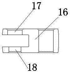
[0028] Based on Embodiment 1, the lancet driver 3 includes a clamping member 28 and a winding member 29, a return spring 30 is wound on the winding member 29, and one end of the return spring 30 is connected to the clamping member 28, The clamping member 28 is provided with a left clamping block 20 and a right clamping block 21, and the distance between the left clamping block 20 and the right clamping block 21 is 6 mm, and the requirements for the clamping point of the lancet device are relatively low, and the clamping The point is larger than that of Example 1, and the wear resistance is better.
Embodiment 3
[0030] Based on Embodiment 1, the lancet driver 3 includes a clamping member 28 and a winding member 29, a return spring 30 is wound on the winding member 29, and one end of the return spring 30 is connected to the clamping member 28, The clamping member 28 is provided with a left clamping block 20 and a right clamping block 21, and the distance between the left clamping block 20 and the right clamping block 21 is 8 mm, which has lower requirements on the clamping point of the lancet device, and the clamping The larger the point, the better the abrasion resistance, but the less flexibility.
PUM
 Abstract
Description
Claims
Application Information
 - R&D Engineer
- R&D Manager
- IP Professional
- Industry Leading Data Capabilities
- Powerful AI technology
- Patent DNA Extraction
Browse by: Latest US Patents, China's latest patents, Technical Efficacy Thesaurus, Application Domain, Technology Topic.
© 2024 PatSnap. All rights reserved.Legal|Privacy policy|Modern Slavery Act Transparency Statement|Sitemap