Semi-automatic dyeing cleaning system

A semi-automatic, dyeing roller technology, applied in the field of textile printing and dyeing, can solve the problems of time-consuming and labor-intensive cleaning of dyeing rollers, and achieve the effects of saving manpower, high cleaning efficiency and reducing labor intensity.

Inactive Publication Date: 2017-08-04
CHANGXING COUNTY DAWEI TEXTILE CO LTD
View PDF0 Cites 4 Cited by
  • Summary
  • Abstract
  • Description
  • Claims
  • Application Information

AI Technical Summary

Problems solved by technology

[0003] The purpose of the present invention is to provide a semi-automatic dyeing and cleaning system for the deficiencies of the prior art, which controls the working state of the dyeing mechanism and the cleaning mechanism based on the force on the dyeing roller, and performs automatic cleaning of the dyeing roller, greatly improving the cleaning efficiency. Efficiency, solving the technical problem of time-consuming and labor-intensive cleaning of dyeing rollers in the prior art

Method used


Image

  • Semi-automatic dyeing cleaning system
  • Semi-automatic dyeing cleaning system
  • Semi-automatic dyeing cleaning system

Examples


Embodiment 1

[0062] The embodiments are described below with reference to the accompanying drawings. The embodiments shown below do not limit the invention content described in the claims. required for the solution.

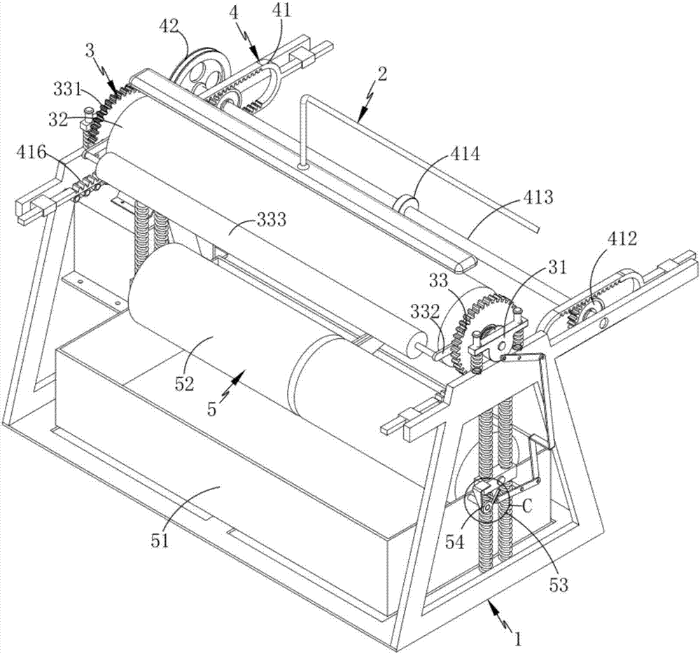
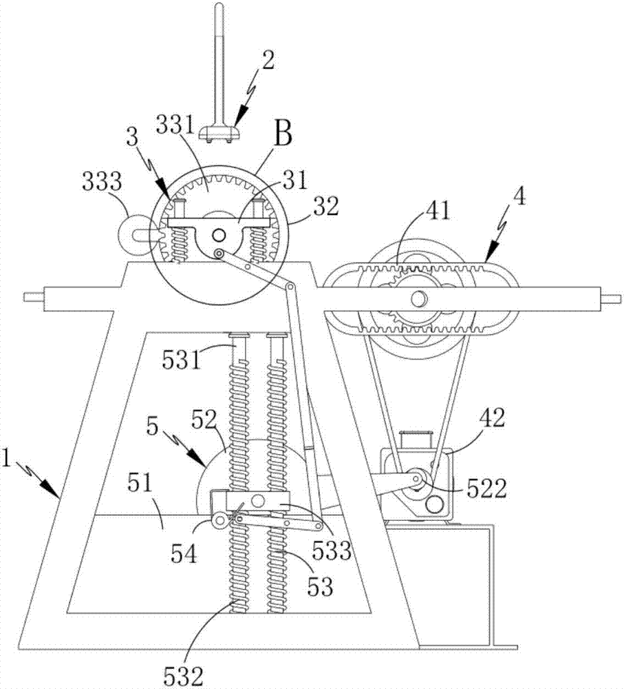
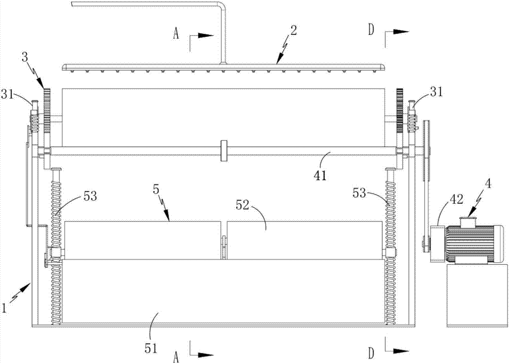
[0063] Such as figure 1 , 2, 3, a semi-automatic dyeing cleaning system, including a frame 1 and a dyeing mechanism 2, also includes:

[0064] A dyeing mechanism 3, the two ends of the dyeing mechanism 3 are respectively arranged on the frame 1 through the first elastic component 31, and are located below the spraying mechanism 2;

[0065] The transmission mechanism 4 includes a transmission assembly 41 arranged on the dyeing frame 1 and a drive assembly 42 that drives the transmission assembly 41 for reciprocating motion; and

[0066] Cleaning mechanism 5, described cleaning mechanism 5 is arranged on the below of described dyeing mechanism 3, and it comprises:

[0067] Washing tank 51;

[0068] A cleaning assembly 52, the cleaning assembly 52 is located inside the wash...

Embodiment 2

[0102] Components that are the same as or corresponding to those in the first embodiment use the reference numerals corresponding to those in the first embodiment. For the sake of simplicity, only the differences from the first embodiment are described below. The difference between this embodiment two and embodiment one is: as Figure 4 As shown, it also includes a linkage assembly 6 installed on the frame 1 and arranged on the same side as the locking assembly 54. The linkage assembly 6 includes:

[0103] A first swing rod 61, the first swing rod 61 is rotatably mounted on the frame 1 and is rotatably connected with the mounting block 313;

[0104] The second swing rod 62, the second swing rod 62 is rotatably mounted on the washing tank 51, one end of which is rotatably connected with the first swing rod 61 via a traction link 63, and the other end is connected with the locking assembly 54 contact settings.

[0105] Install the linkage assembly 6 on the same side of the loc...


PUM


Abstract

The invention relates to a semi-automatic dyeing and cleaning system, which includes a frame and a dyeing mechanism, and also includes a dyeing mechanism and a transmission mechanism that are respectively arranged on the frame through first elastic components at both ends and located below the spraying mechanism. And a cleaning mechanism arranged below the dyeing mechanism, the cleaning mechanism includes a water washing tank, a cleaning assembly located inside the water washing tank, and a second elastic spring that is symmetrically arranged at both ends of the cleaning assembly and installed in cooperation with it. Components and rotating installations on the washing tank are used to control the cleaning components and lock components positioned inside the washing tank; the working conditions of the dyeing mechanism and cleaning mechanism are controlled by the force on the dyeing roller, and the automatic cleaning of the dyeing roller is carried out , greatly improve the cleaning efficiency, and solve the technical problem of time-consuming and labor-intensive cleaning of dyeing rollers in the prior art.

Description

technical field [0001] The invention relates to the field of textile printing and dyeing, in particular to a semi-automatic dyeing cleaning system. Background technique [0002] The textile industry is an important industry of our country's national economy. For a long time, the textile industry has made significant contributions to the development of the national economy, solving the problem of people's clothing, and earning foreign exchange through exports. The dyeing and finishing industry as a connecting bridge undoubtedly plays an important role in this industry. status. The dyeing and finishing industry is the key to deep processing, finishing and added value of textiles. It is the link between textile fibers, raw yarns, and gray cloths processed into final products entering the consumer market, and plays an important role in promoting the common development of products; for dyeing For the industry, the application of the dyeing roller is essential. However, after the...

Claims


Application Information

Patent Timeline
Patent Type & Authority Applications(China)
IPC IPC(8): D06B23/30D06B1/14
CPCD06B23/30D06B1/14
Inventor 臧伟
Owner CHANGXING COUNTY DAWEI TEXTILE CO LTD
Why Eureka
Try Eureka