Pavement cutting apparatus used for road and bridge construction

A cutting device and bridge construction technology, which is applied in the direction of roads, roads, road repair, etc., can solve the problems of low cutting rate, time-consuming and laborious, and flying dust.

Inactive Publication Date: 2017-08-04
李建云
View PDF9 Cites 6 Cited by
  • Summary
  • Abstract
  • Description
  • Claims
  • Application Information

AI Technical Summary

Problems solved by technology

[0010] In order to overcome the shortcomings of the existing road surface cutting device for road and bridge construction, dust flying everywhere, low cutting speed, time-consuming and labor-intensive, the technical problem to be solved by the present invention is to provide a cutting device that does not fly dust and has a high cutting speed. , Time-saving and labor-saving road surface cutting device for road and bridge construction

Method used


Image

  • Pavement cutting apparatus used for road and bridge construction
  • Pavement cutting apparatus used for road and bridge construction
  • Pavement cutting apparatus used for road and bridge construction

Examples


Embodiment 1

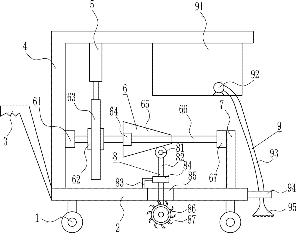
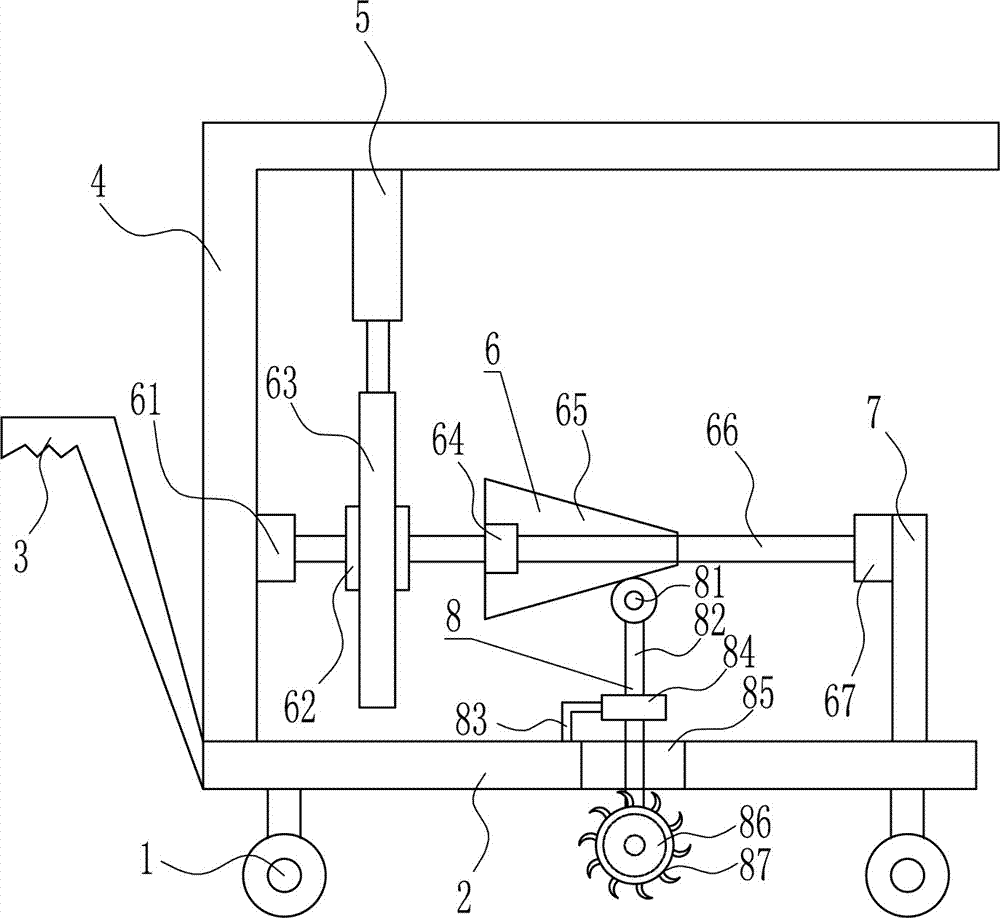
[0040] A road surface cutting device for road and bridge construction, such as Figure 1-6 As shown, it includes a universal wheel 1, a base plate 2, a push handle 3, a left bracket 4, a cylinder 5, a driving device 6, a right bracket 7 and a cutting device 8. The bottom plate 2 is provided with a universal wheel 1, and the left end of the base plate 2 is provided with a Push handle 3, left support 4 is provided on the left side of the top of the base plate 2, a cylinder 5 is provided on the left side of the top of the left support 4, a driving device 6 is provided at the middle part of the right side of the left support 4, a right support 7 is provided on the right side of the top of the base plate 2, and the base plate 2 middle part is provided with cutting device 8.

Embodiment 2

[0042] A road surface cutting device for road and bridge construction, such as Figure 1-6 As shown, it includes a universal wheel 1, a base plate 2, a push handle 3, a left bracket 4, a cylinder 5, a driving device 6, a right bracket 7 and a cutting device 8. The bottom plate 2 is provided with a universal wheel 1, and the left end of the base plate 2 is provided with a Push handle 3, left support 4 is provided on the left side of the top of the base plate 2, a cylinder 5 is provided on the left side of the top of the left support 4, a driving device 6 is provided at the middle part of the right side of the left support 4, a right support 7 is provided on the right side of the top of the base plate 2, and the base plate 2 middle part is provided with cutting device 8.

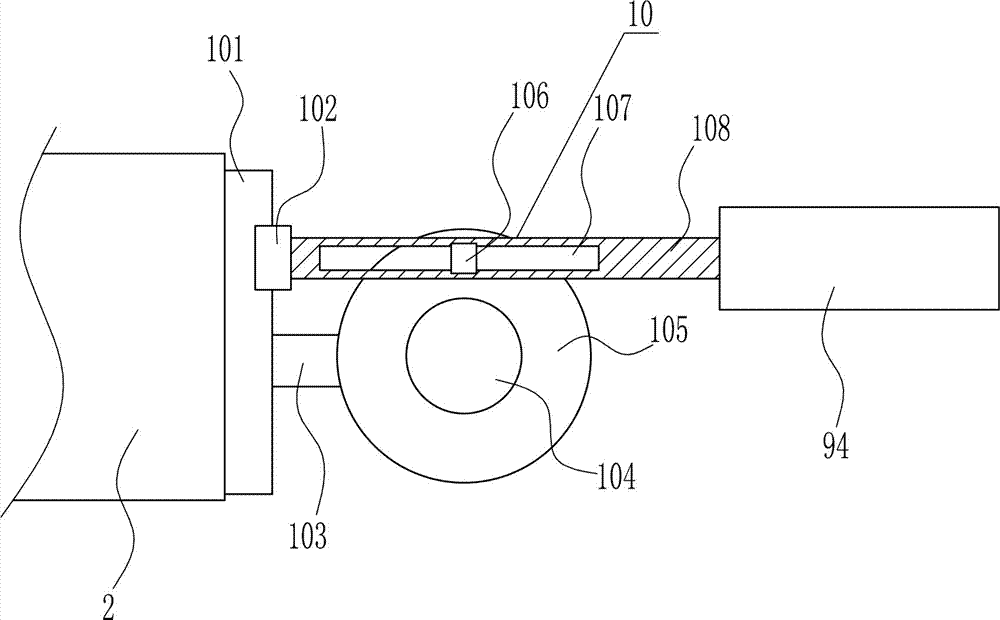
[0043] Driving device 6 comprises left bearing seat 61, gear 62, rack 63, nut 64, tapered block 65, screw rod 66 and right bearing seat 67, and left support 4 right side middle part is provided with left beari...

Embodiment 3

[0045] A road surface cutting device for road and bridge construction, such as Figure 1-6 As shown, it includes a universal wheel 1, a base plate 2, a push handle 3, a left bracket 4, a cylinder 5, a driving device 6, a right bracket 7 and a cutting device 8. The bottom plate 2 is provided with a universal wheel 1, and the left end of the base plate 2 is provided with a Push handle 3, left support 4 is provided on the left side of the top of the base plate 2, a cylinder 5 is provided on the left side of the top of the left support 4, a driving device 6 is provided at the middle part of the right side of the left support 4, a right support 7 is provided on the right side of the top of the base plate 2, and the base plate 2 middle part is provided with cutting device 8.

[0046] Driving device 6 comprises left bearing seat 61, gear 62, rack 63, nut 64, tapered block 65, screw rod 66 and right bearing seat 67, and left support 4 right side middle part is provided with left beari...


PUM


Abstract

The invention relates to a pavement cutting apparatus, and especially relates to a pavement cutting apparatus used for road and bridge construction. A technical problem to be solved in the present invention is to provide the pavement cutting apparatus used for road and bridge construction, having the advantages of no dust flying during cutting, high cutting rate, and time and labor saving. The pavement cutting apparatus used for road and bridge construction comprises universal wheels, a baseboard, a pusher, a left support, a cylinder and a driving device; and the bottom of the baseboard is provided with the universal wheels, the pusher is arranged at the left end of the baseboard, the left support is arranged at the left side of the top of the baseboard, the cylinder is arranged at the left side of the top in the left support, the driving mechanism is arranged at the middle portion of the right side of the left support, a right support is arranged at the right side of the top of the baseboard, and a cutting device is arranged at the middle portion of the baseboard. The pavement cutting apparatus used for road and bridge construction has the advantages of no dust flying during cutting, high cutting rate, and time and labor saving.

Description

technical field [0001] The invention relates to a road surface cutting device, in particular to a road surface cutting device for road and bridge construction. Background technique [0002] Road bridges are generally composed of several parts such as roadbed, road surface, bridge, tunnel engineering and traffic engineering facilities. [0003] 1. Roadbed engineering: The roadbed is a linear structure built with soil or stone. It bears its own weight of rock and soil and the gravity of the road surface, as well as the driving load transmitted by the road surface, and is an important part of the entire road structure. Highway subgrade mainly includes several parts such as subgrade body, side slope, side ditch and other auxiliary facilities. [0004] 2. Pavement engineering: Pavement is a layered structure that is paved in layers on the roadbed with various road materials or mixtures for vehicles to drive. Its function is to ensure that the car can run all-weather, stable, h...

Claims


Application Information

Patent Timeline
Patent Type & Authority Applications(China)
IPC IPC(8): E01C23/09
CPCE01C23/0933E01C2301/50
Inventor 不公告发明人
Owner 李建云
Why Eureka
Try Eureka