Defoaming device for engine oil inside crank case of engine

A defoaming device, crankcase technology, applied in engine components, engine lubrication, machine/engine, etc., can solve problems such as oil foaming, and achieve the effect of preventing splashing

Active Publication Date: 2017-08-04
CHINA NORTH ENGINE INST TIANJIN
View PDF5 Cites 0 Cited by
  • Summary
  • Abstract
  • Description
  • Claims
  • Application Information

AI Technical Summary

Problems solved by technology

[0004] In view of this, the present invention aims to propose a kind of machine oil defoaming device in the engine crankcase, to solve the problem of machine oil foaming caused by high rotating speed in the crankcase

Method used


Image

  • Defoaming device for engine oil inside crank case of engine
  • Defoaming device for engine oil inside crank case of engine

Examples


Embodiment Construction

[0023] It should be noted that, in the case of no conflict, the embodiments of the present invention and the features in the embodiments can be combined with each other.

[0024] The present invention will be described in detail below with reference to the accompanying drawings and examples.

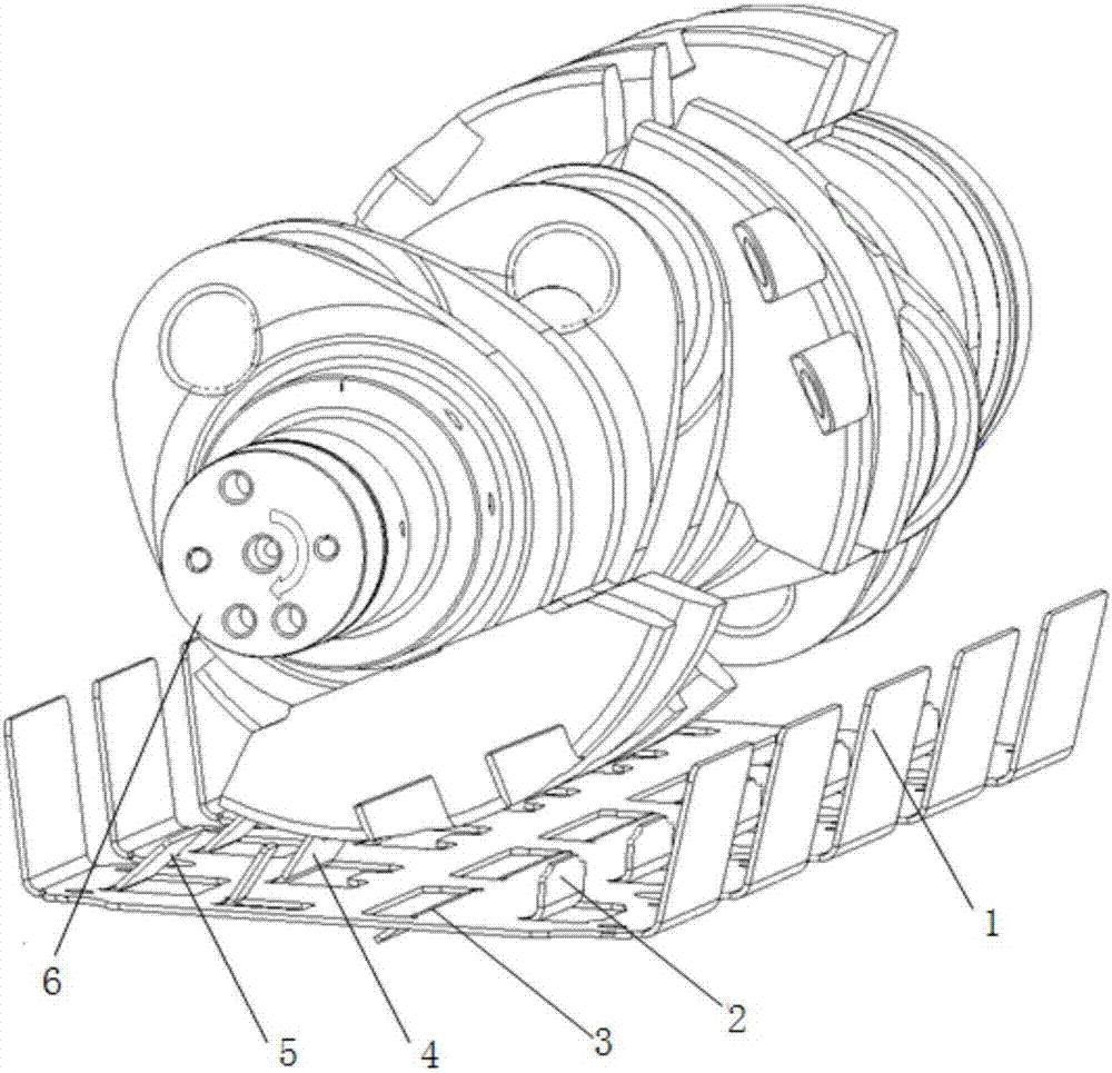
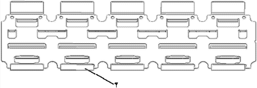
[0025] Such as figure 1 and figure 2 As shown, an engine oil defoaming device in the crankcase of an engine includes a structural body 1, the structural body 1 is located below the crankshaft 6, and a plurality of first slots 2, second slots 2 are respectively arranged on the structural body 1. slot 3, the third slot 4 and the fourth slot 5, the first slot 2 is located at the front end of the structural body 1 and corresponds to the position of the crankshaft connecting rod journal, the second slot 3 is located at the The middle of the structural body 1 corresponds to the position of the crankshaft connecting rod journal, the third slot 4 is located in the middle of the structural bod...


PUM

PropertyMeasurementUnit
thicknessaaaaaaaaaa

Abstract

The invention provides a defoaming device for engine oil inside a crank case of an engine. The defoaming device comprises a structure body; the structure body is located below a crank; multiple first open slots, multiple second open slots, multiple third open slots and multiple fourth open slots are arranged and formed in the structure body; the first open slots are located in the front end of the structure body and correspond to the position of a journal of a crank connecting rod; the second open slots are located in the front side of the middle of the structure body and correspond to the position of the journal of the crank connecting rod; the third open slots are located in the back side of the middle of the structure body and correspond to the position of a balancing weight of the crank; the fourth open slots are located in the back end of the structure body and correspond to the position of the journal of the crank connecting rod; and flow guide plates are arranged on the four kinds of open slots. The defoaming device has the beneficial effects as follows: open slot structures at different angles are formed in different positions of the structure body according to the rotation direction of the crank of the engine, air bubbles produced by air flows produced due to movement of the crank are avoided, the flow direction of the engine oil falling back freely is guided, and splashing is prevented.

Description

technical field [0001] The invention belongs to the technical field of engine oil defoaming, in particular to an engine oil defoaming device in an engine crankcase. Background technique [0002] With the continuous improvement of the power level of modern engines, the average effective pressure, the maximum combustion pressure and the engine speed are all increased. The engine speed increases in direct proportion to the air content of the engine oil. The oil mist concentration and foam in the crankcase increase significantly, which directly affects the engine lubrication and cooling effect, reduces the oil pressure, deteriorates the wear resistance, and even causes air resistance in the pipeline to interrupt the oil supply. Therefore, strengthening the defoaming technology of the engine is the The design elements that must be considered in research and development are important factors to ensure the normal operation of the engine. [0003] In the prior art, in order to prev...

Claims


Application Information

Patent Timeline
Patent Type & Authority Applications(China)
IPC IPC(8): F01M9/00B01D19/02
CPCB01D19/0073B01D19/02F01M9/00
Inventor 张云静曾壮李志鹏杨贵春刘艳利张强冯垣洁高云峰陈卓群吕国学吴雁玲
Owner CHINA NORTH ENGINE INST TIANJIN
Why Eureka
Try Eureka