Rock joint shearing test device

A technology for rock joints and shear testing, which is applied to measuring devices, using a stable shear force to test the strength of materials, instruments, etc. It can solve the problems of shearing phenomenon, inconvenient handling and installation, and heavy shear box weight.

Inactive Publication Date: 2017-08-04
TONGJI UNIV
View PDF5 Cites 6 Cited by
  • Summary
  • Abstract
  • Description
  • Claims
  • Application Information

AI Technical Summary

Problems solved by technology

In the existing rock joint shear test devices, in some shear devices, the joint sample will collide with the shear box during the movement process, resulting in errors in the shear results; in some shear devices, there is a large friction between the upper and lower shear boxes force, so that the shear load acting on the joint surface changes, which is difficult to measure; some shear test devices limit the shear direction of the joint surface, and there will be a shear phenomenon, which is inconsistent with the shear deformation of the joint surface in actual engineering ;In addition, due to the heavy weight of the shear box, it is inconvenient during the handling and installation process

Method used


Image

  • Rock joint shearing test device
  • Rock joint shearing test device
  • Rock joint shearing test device

Examples


Embodiment 1

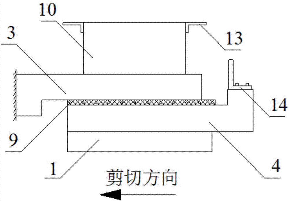
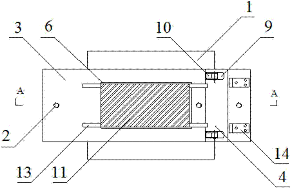
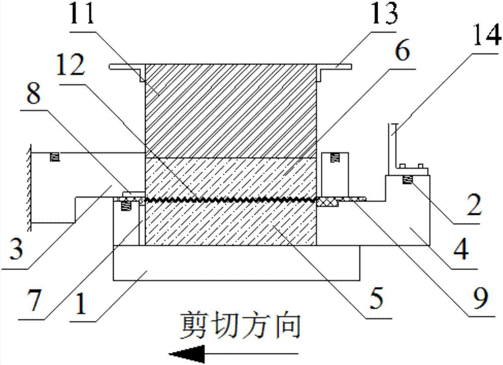
[0029] A kind of rock joint shear test device, its structure is as follows Figure 1 to Figure 6 As shown, the rock joint shear test device includes a base 1, which is arranged below the lower shear box 4, and the two are made into a rigid body by machining. The upper shear box 3 covers the top of the lower shear box 4, and the middle part of both is provided with a cavity 7, which is used to place rock joint samples after overlapping, and a piece of metal block 11 is pressed above the rock joint samples. The central axis of the rock joint sample is a joint surface 12 , and the rock joint sample is divided into a rock joint upper shear block 5 and a rock joint upper shear block 6 . Two internally threaded holes 2 are provided at the two ends of the central axis of the upper surface of the upper shear box 3 and the lower shear box 4, and the bolts with lifting holes are screwed into the internally threaded holes 2 to fix them, and the upper and lower shear boxes can be moved by...


PUM


Abstract

The invention relates to a rock joint shearing test device. The device comprises an upper shear box and a lower shear box which are symmetrically arranged, wherein cavities for placing a rock joint sample are respectively formed in the middle part of the upper shear box and the lower shear box; the lower shear box is fixedly arranged on a base; a metal block presses on the top of the rock joint sample; grooves are arranged in the middle part of the upper shear box and the lower shear box and communicated with one ends of the cavities; the widths of the grooves are same as the widths of the cavities; and the lengths of the grooves in the shear direction are slightly greater than the shear displacement in the test. Compared with the prior art, the device has the beneficial effects that channels are arranged in places where the upper and the lower shear boxes are in contact and roller rows are placed in the channels, the upper shear box is elevated by utilizing the roller rows and space equivalent to the joint surface roughness between the upper and the lower shear boxes is left; and the contact area of the upper and the lower shear boxes can be reduced after arranging the roller rows, and the influence of the frictional resistance between the two shear boxes in the shear moving process on the test is reduced.

Description

technical field [0001] The invention relates to a rock joint seepage test, in particular to a rock joint shear test device. Background technique [0002] Jointed rock mass is a complex rock mass often encountered in various rock mass projects such as underground caverns, tunnels, mining, water conservancy and hydropower, and slopes. During the geological process, a large number of joints of different scales are produced in the rock mass. Compared with the intact rock block, the shear strength of the joint is lower, and it is a weak surface in the rock mass, so the mechanical properties of the rock mass depend to a large extent on the shear mechanical properties of the joint. [0003] In actual engineering, the shearing process of the joint surface is caused by many factors. Factors such as normal load, shear load, rock material, and three-dimensional shape of the joint surface all affect the joint shearing. In order to obtain reliable test results in the laboratory, the sh...

Claims


Application Information

Patent Timeline
Patent Type & Authority Applications(China)
IPC IPC(8): G01N3/24G01N3/02
CPCG01N3/24G01N3/02
Inventor 夏才初庄小清钱鑫桂洋喻强锋
Owner TONGJI UNIV
Why Eureka
Try Eureka