Microwave tube experiment device

The technology of an experimental device and a shock tube is applied to measuring devices, material analysis through optical means, instruments, etc. It can solve the problems of easy drop damage, inconvenient observation, and poor air tightness of the clamping device, and achieve the goal of installation Convenient and fast, compact structure, easy to observe the effect of the experiment

Pending Publication Date: 2017-08-04
NORTH CHINA ELECTRIC POWER UNIV (BAODING)
View PDF4 Cites 9 Cited by
  • Summary
  • Abstract
  • Description
  • Claims
  • Application Information

AI Technical Summary

Problems solved by technology

[0004] The purpose of the present invention is to provide a shock tube experimental device, which solves the problems that the prior art e

Method used


Image

  • Microwave tube experiment device
  • Microwave tube experiment device
  • Microwave tube experiment device

Examples


Embodiment Construction

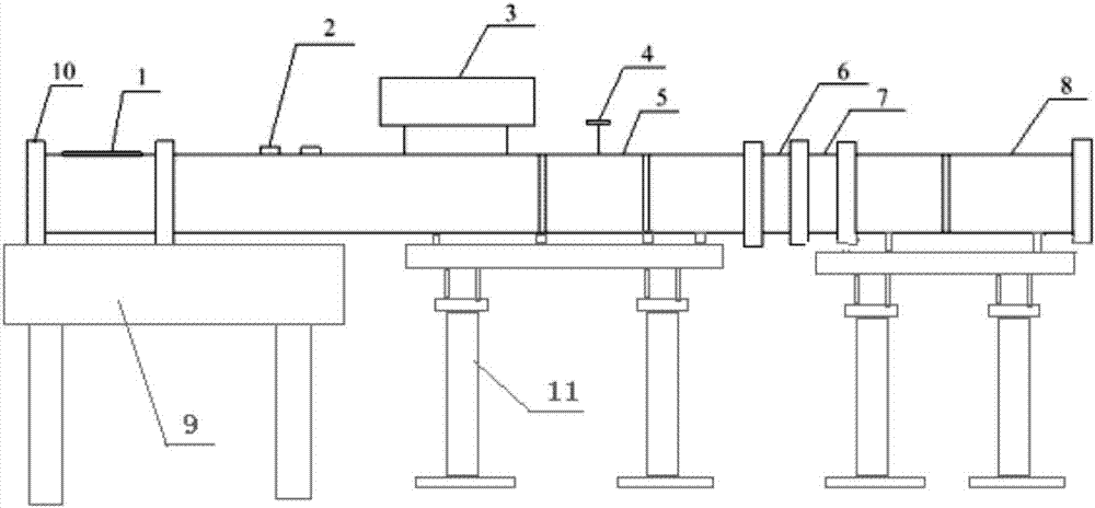
[0027] Such as figure 1 As shown, a shock tube experimental device, the shock tube is installed on the optical platform 9 and the support frame 11 through the tube body fixing device 12, the shock tube includes an experimental section 1, a low pressure section 5 and a high pressure section 8. The experimental section 1, the low-pressure section 5 and the high-pressure section 8 are arranged in sequence, the shock tube end caps 10 are installed at both ends of the shock tube, and the low-pressure section 5 is provided with a pressure sensor 2 and a gas mixture chamber 3 And the tap 4, between the low-pressure section 5 and the high-pressure section 8 is a medium-pressure section, and the medium-pressure section is provided with a molecular pump air extraction section 6 and a clamping device 7;

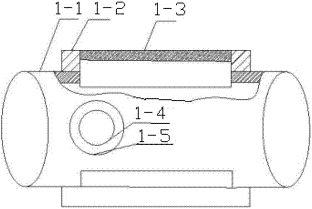
[0028] Such as figure 2 As shown, the experimental section 1 includes an experimental section tube body 1-1, and observation windows are symmetrically arranged on the front and rear s...


PUM

PropertyMeasurementUnit
Sizeaaaaaaaaaa

Abstract

The invention discloses a microwave tube experiment device. A microwave tube is arranged on an optical platform and a support, and comprises an experiment section, a low voltage section, a mediate voltage section and a high voltage section which are arranged in sequence; microwave tube end caps are arranged at two ends of the microwave tube; a pressure sensor, a mixed gas chamber and a tap are arranged on the low voltage section; a molecular pump extraction section and a capsule device are arranged on the mediate voltage section; the experiment section comprises an experiment section tube body, and observing windows are symmetrically formed in front and rear walls of the experiment section tube body; the pressure sensor comprises a PCB pressure sensor, a pressure sensor gland, a first connecting part, a second connecting part and a copper ring; a seal ring is arranged on the plane, matched with the second connecting part, of the first connecting part; two flanges for connecting are arranged on the capsule device, and a capsule holder is arranged between the two flanges. The microwave tube experiment device is smart in idea, compact in structure, convenient and quick to assemble and safe and stable to use, and is convenient for observing experiment effects.

Description

technical field [0001] The invention relates to the technical field of experimental equipment, in particular to a shock tube experimental device. Background technique [0002] In the current study, the chemical shock tube can provide a constant temperature and pressure reaction environment, which is an ideal reactor for fuel oxidation research. During the experiment, the driving gas (helium, nitrogen, etc.) is filled in the high-pressure section first, and the experimental combustible gas is filled in the low-pressure section. After reaching a certain pressure difference, the diaphragm ruptures to generate a shock wave, and the shock wave reaches the pressure sensor in the low-pressure section. The optical window is reflected by the end face to form a reflected shock wave, and the reflected area can provide a high temperature and high pressure experimental environment. [0003] In the shock tube commonly used in the prior art, only three observation holes with a diameter of...

Claims


Application Information

Patent Timeline
IPC IPC(8): G01N31/12G01N21/01
CPCG01N21/01G01N31/12
Inventor 李金芳李永华
Owner NORTH CHINA ELECTRIC POWER UNIV (BAODING)
Why Eureka
Try Eureka