
Coiling device and method for spiral heat exchange tube core in heat exchanger

A technology of heat exchange tube cores and heat exchangers, applied in heat exchange equipment, etc., can solve the problems of low production efficiency, low accuracy, inconvenient use, etc., achieve high production efficiency, convenient operation, and avoid the effect of calculation process

Inactive Publication Date: 2017-08-08
WEIHAI VOCATIONAL COLLEGE
View PDF1 Cites 3 Cited by
  • Summary
  • Abstract
  • Description
  • Claims
  • Application Information

AI Technical Summary

Problems solved by technology

[0003] The present invention aims to solve the technical problems of low precision, inconvenient use and low production efficiency of existing coilers used for spiral heat exchange tubes, and provides a heat exchanger internal coiler with high precision, convenient use and high production efficiency. Rolling device and method for spiral heat exchange tube core

Method used


Image

  • Coiling device and method for spiral heat exchange tube core in heat exchanger
  • Coiling device and method for spiral heat exchange tube core in heat exchanger
  • Coiling device and method for spiral heat exchange tube core in heat exchanger

Examples


Embodiment Construction

[0053] Referring to the accompanying drawings, the present invention will be further described in detail with specific embodiments.

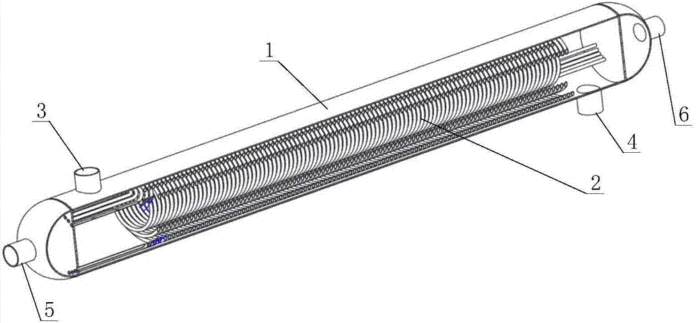
[0054] Such as Figure 1-2 As shown, the heat exchanger includes a shell 1, and a three-layer spiral heat exchange tube core 2 is installed in the shell 1. The housing 1 is provided with a heating medium inlet 3 , a heating medium outlet 4 , a heated fluid inlet 5 and a heated fluid outlet 6 .

[0055] Such as Figure 5-8 As shown, the rolling device of the spiral heat exchange tube core includes a body 7, a roller bearing seat 11, a spindle deceleration servo motor 15, a feed servo motor 16, a touch control panel 12 and a main controller are installed on the body 7, and the roller 8 One end is connected with the roller bearing seat 11, and the end face of the other end is provided with three round holes 8-1. The sprocket shaft of sprocket wheel 13 is installed on the body 7 by bearing seat, and the sprocket wheel shaft of sprocket wheel 13 is ...


PUM


Abstract

The invention relates to a coiling device and method for a spiral heat exchange tube core in a heat exchanger and solves the technical problems of low accuracy, inconvenience in use and low production efficiency of the existing tube coiling machine for a spiral heat exchange tube. The coiling device comprises a machine body, a rotary drum, a main shaft speed reducing servo motor, a feeding servo motor, a lead screw, a nut seat, a compression roller frame base, a compression roller frame, an air cylinder, a compression roller, two guide rails, a touch control screen and a master controller; two ends of the rotary drum are connected with the machine body by bearing seats, and the main shaft speed reducing servo motor is connected with one end of the rotary drum through a driving mechanism; two ends of the lead screw are connected with the machine body by bearing seats; an output shaft of the feeding servo motor is connected with the lead screw by a driving mechanism; the nut seat is connected with the lead screw; the compression roller frame base is fixedly connected with the nut seat; the compression roller frame is connected with the compression roller frame base; the compression roller is connected with the compression roller frame; the air cylinder is connected between the compression roller frame base and the compression roller frame; and the two guide rails are connected to the machine body side by side. The coiling device is widely used for coiling the spiral heat exchange tube.

Description

technical field [0001] The invention relates to the technical field of spiral wound tube heat exchangers, in particular to a rolling device and method for a spiral heat exchange tube core in a heat exchanger. Background technique [0002] The spiral thread tube heat exchanger consists of two parts: core and shell. The core is mainly composed of spiral heat exchange tubes. The shell is composed of cylinder and head. The upper and lower heads have two openings. Referring to the Chinese utility model patent with the authorized announcement number CN204866968U, the spiral heat exchange tube is processed by a tube winding machine. The existing tube winding machine has technical defects that cannot accurately control the shape of the helix. In addition, there is a problem with the spiral stainless steel The calculation of the number of layers and rolling diameter of the tube is cumbersome, inconvenient to use and low in production efficiency. Contents of the invention [0003] ...

Claims


Application Information

Patent Timeline
Patent Type & Authority Applications(China)
IPC IPC(8): B21D53/06B21D11/06
CPCB21D11/06B21D53/06Y02P70/10
Inventor 马春峰
Owner WEIHAI VOCATIONAL COLLEGE
Learn More