Steel beam machining device

A technology for processing devices and steel beams, applied in auxiliary devices, metal processing equipment, manufacturing tools, etc., can solve problems affecting construction efficiency, difficulty in ensuring consistent welding quality, affecting steel beam processing quality and processing efficiency, etc.

Inactive Publication Date: 2017-08-08
河南华斯豪智能科技有限公司
View PDF5 Cites 1 Cited by
  • Summary
  • Abstract
  • Description
  • Claims
  • Application Information

AI Technical Summary

Problems solved by technology

[0002] The current processing of steel beams is generally made by manual processing, which requires a large number of construction personnel to operate, and the welding quality is not easy to ensure consistency, which seriously affects the processing quality and efficiency of steel beams.
Especially longer steel beams, for example: steel beams with a length of more than 10 meters, need the cooperation of multiple workers to complete, which greatly affects the construction efficiency, and the construction intensity is relatively high, which is not conducive to the processing of steel beams

Method used


Image

  • Steel beam machining device
  • Steel beam machining device
  • Steel beam machining device

Examples


Embodiment 1

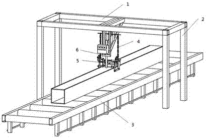
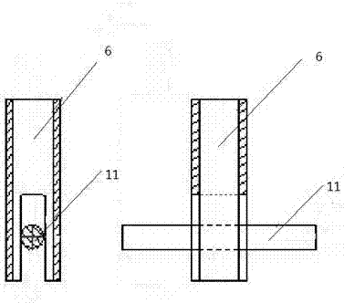
[0010] Embodiment 1, a kind of steel beam processing device, it comprises gate-shaped support 2, conveying roller 3, is provided with gate-shaped support 2 matched with conveying roller, is provided with beam 1 on the gate-shaped support, is provided with traction on beam 1 Rod 6, the bottom groove of draw bar 6 is fixed with the pull bar 17 of welding trolley, is provided with pulley on crossbeam, is equipped with chain 4 in the pulley, and one end of chain 4 is fixedly connected with drag bar 17 on welding trolley 5, The welding trolley is provided with a welding torch.

[0011] In this embodiment, the steel beam to be welded is placed on the transfer roller 3, the part to be welded corresponds to the welding torch, the transfer roller 3 is started, the steel beam body moves, and the welding device is opened at the same time, and the welding trolley 5 is operated by the drawbar. Can ride on the steel beam body and slide, so that the welding torch on the welding trolley 5 can...

Embodiment 2

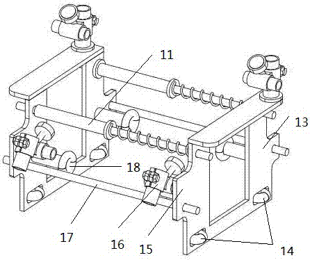
[0012] Embodiment 2, this embodiment further defines the structure of the welding trolley 5 on the basis of the embodiment 1. The welding trolley is as follows: a fixed rod 11 is provided between two support plates 13, and The two ends of the support plate 13 are respectively provided with fixed clamping plates 15, and two corresponding fixed clamping plates 15 are fixed with drag rods 17; Bolts are provided with running wheels 14 on both sides of the bottom of the support plate 13, guide rollers 18 are provided at the middle of the base plate, and a welding torch fixing cartridge 16 is provided at the end of the support plate 13, and the welding torch clamp is fixed on the fixing cartridge. 16; in this embodiment, the distance between the two support plates 13 can be adjusted through the screw and bolt devices on the fixed rod 11 and the drag rod 17, so as to adapt to the processing needs of steel beams of different sizes.


PUM


Abstract

The invention provides a steel beam machining device. The steel beam machining device comprises a portal support and conveying rollers. The portal support is matched with the conveying rollers. The portal support is provided with a cross beam. A traction rod is arranged on the cross beam. A bottom groove of the traction rod is clamped and fixed to drawing rods of a welding trolley. Pulleys are arranged on the cross beam, and chains are assembled inside the pulleys. One end of each chain is fixedly connected with the corresponding drawing rod of the welding trolley. A welding gun is arranged on the welding trolley. According to the structure of the welding trolley, fixed rods are arranged between two supporting plates, fixed clamping plates are arranged at the two ends of the supporting plates, each drawing rod is fixed to two corresponding fixed clamping plates; the ends of each fixed rod and each drawing rod are both provided with threads and provided with bolts, the two sides of the bottom of each supporting plate are both provided with walking wheels, guide rolling wheels are arranged in the middle of base plates, and welding gun fixing clamping cylinders are arranged at the ends of the supporting plates. The steel beam machining device is high in machining efficiency, stable in machining quality and particularly suitable for machining of long steel beams.

Description

technical field [0001] The invention relates to the processing of steel beams, in particular to a device suitable for processing long steel beams. Background technique [0002] The current steel beam processing is generally made by manual processing, which requires a large number of construction personnel to operate, and the welding quality is not easy to ensure consistency, which seriously affects the processing quality and processing efficiency of the steel beam. Especially longer steel beams, for example: steel beams with a length of more than 10 meters, need the cooperation of multiple workers to complete, which greatly affects the construction efficiency, and the construction intensity is relatively high, which is not conducive to the processing of steel beams . Contents of the invention [0003] The object of the invention is to design a steel beam processing device with reasonable structure and convenient use. [0004] The technical solution of the present inventi...

Claims


Application Information

Patent Timeline
Patent Type & Authority Applications(China)
IPC IPC(8): B23K37/02
CPCB23K37/02B23K37/0211
Inventor 胡文华翟功伟钮艳梅周世委刘富伟王明凯杨彬彬姚志义宋相军李务元
Owner 河南华斯豪智能科技有限公司
Why Eureka
Try Eureka