Variable-mode valve driving system

A driving system and valve technology, applied in the direction of engine components, machines/engines, non-mechanically actuated valves, etc., can solve the problems of difficult processing, complex oil circuit, large quality, etc., and achieve extended service life, low cost and low cost. The effect of emissions

Active Publication Date: 2017-08-08
DALIAN UNIV OF TECH
View PDF8 Cites 21 Cited by
  • Summary
  • Abstract
  • Description
  • Claims
  • Application Information

AI Technical Summary

Problems solved by technology

In addition, this mechanism also has problems such as a large number of moving parts and a large mass caused by both the drive and brake adjustment mechanisms being installed on the rocker arm, which is not conducive to the low energy consumption of the valve drive system; in addition, the motion inertia of the rocker arm is large

Method used


Image

  • Variable-mode valve driving system
  • Variable-mode valve driving system
  • Variable-mode valve driving system

Examples


Embodiment Construction

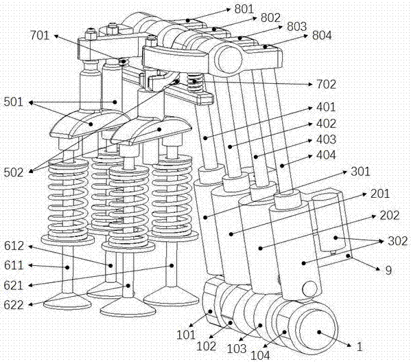
[0033] The invention relates to a variable mode valve drive system. It includes an intake valve assembly and an exhaust valve assembly. It also includes a cam arranged on the camshaft 1, two drive fulcrum components and two brake fulcrum components mounted on a fixed part, push rod, rocker arm, rocker Arm reset mechanism. The cam includes an exhaust brake cam 101, an exhaust drive cam 102, an intake drive cam 103, and an intake brake cam 104. The drive fulcrum assembly includes an exhaust drive fulcrum assembly 201 and an intake drive fulcrum assembly 202. The brake fulcrum assembly It includes an exhaust brake fulcrum assembly 301 and an intake brake fulcrum assembly 302. The push rods include an exhaust brake push rod 401, an exhaust drive push rod 402, an intake drive push rod 403 and an intake brake push rod 404, The rocker arm includes an exhaust brake rocker arm 801, an exhaust drive rocker arm 802, an intake drive rocker arm 803, and an intake brake rocker arm 804. The ...


PUM


Abstract

The invention discloses a variable-mode valve drying system and belongs to the field of engine vale driving, cylinder stopping and auxiliary braking. The variable-mode valve driving system comprises an exhaust braking cam, an exhaust drive cam, a gas inlet drive cam and a gas inlet braking cam, wherein all the cams drive a valve through push rods, rocker arms and the like. The variable-mode valve driving system further comprises an exhaust braking fulcrum assembly, an exhaust drive fulcrum assembly, a gas inlet drive fulcrum assembly and a gas inlet braking fulcrum assembly which are arranged between all the cams and correspond valve assemblies or all the cams and corresponding valve bridge assemblies. Modes of four-stroke driving, two-stroke braking, cylinder stopping and the like are achieved by controlling the states of all the fulcrums, and the purposes of low oil consumption, low emission and efficient braking are achieved. The variable-mode valve driving system is compact in structure, high in reliability and low in cost.

Description

Technical field [0001] The invention relates to a variable mode valve drive system, which belongs to the fields of engine valve drive, cylinder deactivation and auxiliary braking. Background technique [0002] With the rapid increase in the number of engines, energy and environmental issues have become one of the major issues restricting the sustainable development of our country. Because of its ability to effectively reduce engine fuel consumption and emissions, cylinder deactivation technology has attracted much attention. Studies have shown that: completely closing the intake and exhaust valves when the cylinder is stopped can effectively reduce the pumping loss and improve the ability of the cylinder stop technology to reduce fuel consumption and emissions. [0003] People pay more and more attention to vehicle safety, and more and more countries list auxiliary braking systems as one of the necessary accessories for vehicles. However, most of the current auxiliary braking sys...

Claims


Application Information

Patent Timeline
IPC IPC(8): F01L13/06F01L1/26F01L9/02F01L1/24F01L9/10F01L9/14
CPCF01L1/24F01L1/26F01L13/06F01L2001/2433F01L9/14
Inventor 崔靖晨隆武强田华田江平冯立岩王阳刘威
Owner DALIAN UNIV OF TECH
Why Eureka
Try Eureka