Circuit board fault infrared image automatic detection method

An infrared image, automatic detection technology, applied in the field of infrared imaging, can solve the problems of poor image quality, high difficulty, low recognition and positioning accuracy, etc., and achieve the effect of high-precision infrared image registration

Inactive Publication Date: 2017-08-08
AIR FORCE UNIV PLA
View PDF4 Cites 54 Cited by
  • Summary
  • Abstract
  • Description
  • Claims
  • Application Information

AI Technical Summary

Problems solved by technology

[0006] In order to overcome the above-mentioned deficiencies in the prior art, the object of the present invention is a method for automatic detection of infrared images of circuit board faults. In view of the fact that the infrared thermal image itself only has grayscale data and the image quality is poor, the computer is used to automatically judge, identify, and analyze the images. , Positioning is difficult, and the accuracy of identification and positioning is not high. The method of simultaneous acquisition of visible light images and infrared thermal images is used to obtain image information of the working status of the circuit board.

Method used


Image

  • Circuit board fault infrared image automatic detection method
  • Circuit board fault infrared image automatic detection method
  • Circuit board fault infrared image automatic detection method

Examples


Embodiment

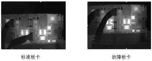
[0105] Check the circuit board of a certain equipment as follows: Figures 17-20 shown.

[0106] Table 1 Temperature analysis of the abnormal working area of ​​the modulator card

[0107] normal board temperature Faulty board temperature Temperature difference area 1 38.6 58.1 19.5 area 2 48.1 41.7 -6.4 area 3 42.0 52.5 10.5

[0108] (1) Area 1 analysis:

[0109] Table 2 Zone 1 temperature analysis

[0110] normal board temperature Faulty board temperature Temperature difference 39.2 56.6 38.3 56.9 38.4 60.8 average 38.6 58.1 19.5

[0111] (2) Area 2 analysis:

[0112] Table 3 Zone 2 temperature analysis

[0113] normal board temperature Faulty board temperature average temperature difference 46.5 41.5 47.3 40.9 49.3 41.6 average 48.1 41.7 -6.4

[0114] (3) Area 3 analysis:

[0115] Table 4 Zone 3 temperature analysis ...


PUM


Abstract

Disclosed is a circuit board fault infrared image automatic detection method. The image information of the working state of a circuit board is obtained by collecting a visible light image and an infrared image simultaneously. First, a visible light image and an infrared image of a circuit board working normally are collected and stored in a database. During detection of the circuit board which malfunctions, circuit board images (including a visible light image and an infrared image) taken are compared with the images under a normal state in the database, and a computer processes the images to find an area and a specific position where a component or line with abnormal temperature is located and automatically make a mark on the visible light image. Thus, automatic detection of a possible faulty component of the circuit board is completed. The technology can be applied to fields such as circuit board maintenance and equipment fault monitoring, and can also be applied to power equipment fault repair, petrochemical pipeline coke plugging, thermal insulation layer fall-off check, railway locomotive axle condition monitoring, fire prevention, flood control, disease prevention and other temperature change related non-contact measurement fields.

Description

technical field [0001] The invention belongs to the technical field of infrared imaging, and in particular relates to an automatic detection method for infrared images of circuit board faults. Background technique [0002] With the continuous development and maturity of infrared imaging technology, the cost of infrared thermal imaging cameras is getting lower and lower, their performance is getting better and better, and their applications are becoming more and more extensive. According to the infrared radiation theory and the temperature measurement principle of the infrared thermal imager, the infrared thermal imager is a device that uses an infrared detector and an optical imaging objective lens to receive infrared radiation from the target to be measured. It can map the infrared radiation energy distribution of different temperature targets , reflected on the photosensitive element of the infrared detector to obtain an infrared thermal image, which corresponds to the the...

Claims


Application Information

Patent Timeline
Patent Type & Authority Applications(China)
IPC IPC(8): G06T7/00G06T7/33G06K9/46
CPCG06T7/001G06T2207/30141G06T2207/10048G06V10/462
Inventor 蒙文李云霞赵尚弘马丽华
Owner AIR FORCE UNIV PLA
Why Eureka
Try Eureka