A dust removal and heat dissipation structure for a switch cabinet

A technology of heat dissipation structure and switchgear, which is applied in the field of switchgear to achieve the effect of ingenious structure

Active Publication Date: 2018-01-09
星凯电气有限公司
View PDF3 Cites 0 Cited by
  • Summary
  • Abstract
  • Description
  • Claims
  • Application Information

AI Technical Summary

Problems solved by technology

[0006] In view of the above situation, in order to solve the problems existing in the use of the existing switchgear, the purpose of the present invention is to provide a dust removal and heat dissipation structure for the switchgear, which can ensure the heat dissipation effect of the switchgear and solve the problem of dustproofing the switchgear. Effect

Method used


Image

  • A dust removal and heat dissipation structure for a switch cabinet
  • A dust removal and heat dissipation structure for a switch cabinet
  • A dust removal and heat dissipation structure for a switch cabinet

Examples


Embodiment Construction

[0020] The specific implementation manners of the present invention will be described in further detail below in conjunction with the accompanying drawings.

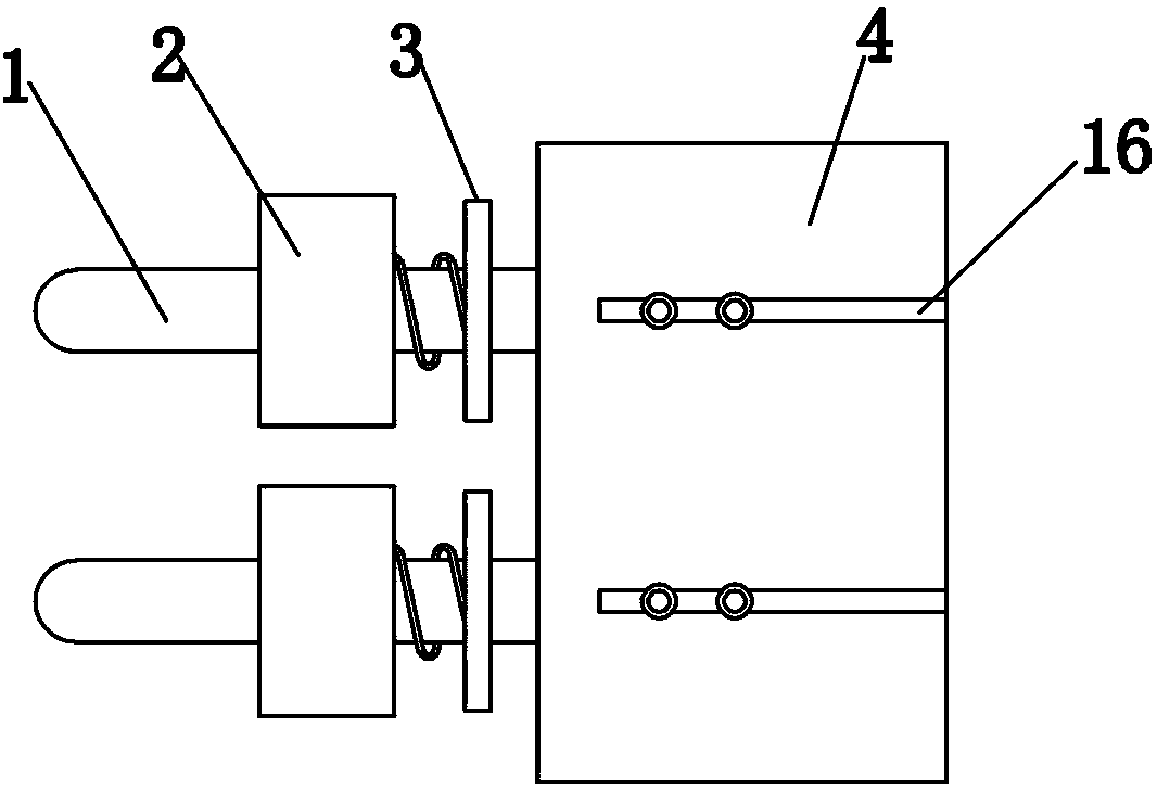
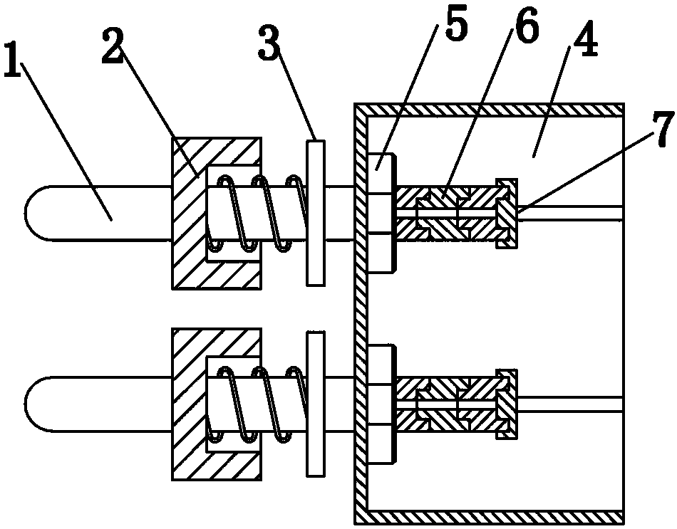
[0021] Depend on Figure 1 to Figure 9 Given, the present invention comprises a vent pipe and a filter box, the vent pipe 1 has through holes running through the left and right ends, one end of the vent pipe 1 is equipped with a stopper 2 and a sealing block 3, the stopper 2 is fixed on the vent pipe 1, sealed The block 3 can slide left and right on the vent pipe 1, and there is a spring set on the vent pipe 1 between the stopper 2 and the sealing block 3;

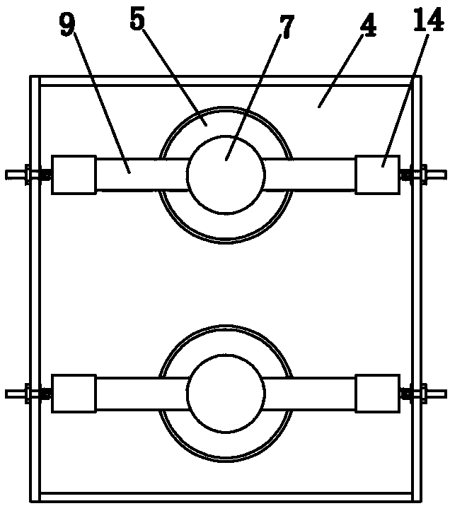
[0022] The other end of the ventilation pipe 1 passes through the side plate of the filter box 4 and is placed in the cavity of the filter box 4, and one end of the ventilation pipe 1 placed in the cavity of the filter box 4 is screwed with a nut 5 and placed in the cavity of the filter box 4 One end of the ventilation pipe 1 has a blind hole communicating with the ...


PUM


Abstract

The invention relates to a dust-removing and heat dissipating structure for a switch cabinet. One end of a ventilation pipe is provided with a stop and and a sealing block which are sleeved therebetween a spring which is sleeved on the ventilation pipe. The other end of the ventilation pipe is disposed inside a cavity of a filtering box and is rotarily provided with a nut, and a blind hole is arranged at one end of the ventilation pipe disposed inside the cavity of the filtering box. The blind hole is provided with a plurality of air inlet heads thereon. The blind hole of the air inlet head which is farthest to the right is provided with a sealing cover thereon. The left and right side of each air inlet head are separately provided with one air inlet pipe which is communicated with the through hole inside the air inlet head, while the other end of the air inlet pipe has an air inlet. The air inlet pipe is sleeved with a column-shaped sponge which is provided with a fixing through hole therein which corresponds to the air inlet pipe. The column-shaped sponge is provided with a filtering hole therein. The diameter of the filtering through hole is greater than that of the fixing through hole. The filtering through hole is provided with multiple filtering layers which are in left and right arrangement. According to the invention, the dust-removing and heat dissipation structure has an ingenious structure, can arrange a plurality of specific air flow channels in the cabinet body, dissipates heat from parts that have large heat to dissipate, and prevents dust from entering to the cabinet body.

Description

technical field [0001] The invention relates to a switch cabinet, in particular to a dust removal and heat dissipation structure for a switch cabinet. Background technique [0002] The switch cabinet is a kind of electrical equipment. The outside line of the switch cabinet first enters the main control switch in the cabinet, and then enters the sub-control switch. Each branch is set according to its needs; such as instruments, automatic control, motor magnetic switches, various AC contactors, etc. Some also have high-voltage room and low-voltage room switchgear, high-voltage busbars, such as power plants, etc., and some also have low-cycle load shedding to ensure the main equipment. [0003] The main function of the switchgear is to open and close, control and protect electrical equipment during the process of power generation, transmission, distribution and power conversion in the power system; the components in the switchgear mainly include circuit breakers, isolating swit...

Claims


Application Information

Patent Timeline
Patent Type & Authority Patents(China)
IPC IPC(8): H02B1/56H02B1/28
CPCH02B1/28H02B1/565
Inventor 史运周
Owner 星凯电气有限公司
Why Eureka
Try Eureka