
Separation system and separation process for low-energy-consumption methanol-to-olefin reaction gas

A technology of methanol-to-olefin and separation system, which is applied in the separation system of low-energy-consumption methanol-to-olefin reaction gas and the field of separation technology

Pending Publication Date: 2020-08-14
HUATING COAL GRP
View PDF7 Cites 0 Cited by
  • Summary
  • Abstract
  • Description
  • Claims
  • Application Information

AI Technical Summary

Problems solved by technology

[0006] The purpose of the present invention is to provide a low energy consumption methanol-to-olefins reaction gas separation system and its separation process, in order to overcome the cumulative circulation of the process condensate condensed after the second stage of the reaction gas compressor in the existing olefins separation technology, The problems caused by large equipment selection, high process energy consumption, and many side reactions, as well as the large consumption of nitrogen per unit time in the drying unit, incomplete separation of process condensate and water, and large steam consumption in the rectification tower reboiler, etc., reduce The investment in olefin separation process equipment is reduced, the consumption of low-pressure nitrogen and low-pressure steam is reduced, and energy consumption is reduced. At the same time, the separation effect of process condensate and water is effectively guaranteed, so as to solve the problems raised in the above-mentioned background technology

Method used


Image

  • Separation system and separation process for low-energy-consumption methanol-to-olefin reaction gas
  • Separation system and separation process for low-energy-consumption methanol-to-olefin reaction gas
  • Separation system and separation process for low-energy-consumption methanol-to-olefin reaction gas

Examples


Embodiment Construction

[0063] The following will clearly and completely describe the technical solutions in the embodiments of the present invention with reference to the accompanying drawings in the embodiments of the present invention. Obviously, the described embodiments are only some, not all, embodiments of the present invention. Based on the embodiments of the present invention, all other embodiments obtained by persons of ordinary skill in the art without making creative efforts belong to the protection scope of the present invention.

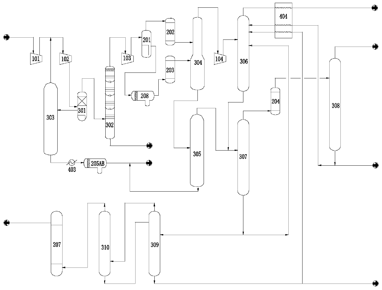
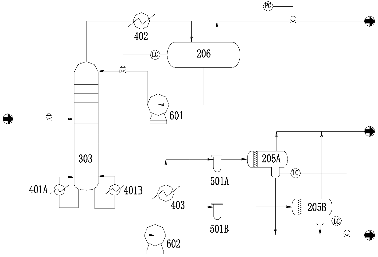
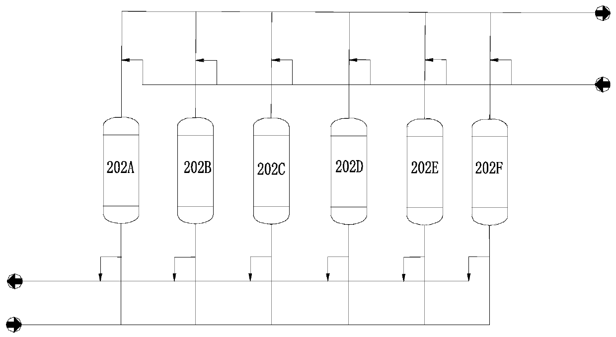
[0064] see Figure 1~4 , in an embodiment of the present invention, a low-energy methanol-to-olefins reaction gas separation system, each device is connected through a pipeline, the first stage of the reaction gas compressor 101, the second stage of the reaction gas compressor 102, and the third stage of the reaction gas compressor 103 pass through the pipeline to the connection; the outlet of the second section 102 of the reaction gas compressor is connected ...


PUM


Abstract

The invention relates to the field of coal-based methanol-to-olefin in the novel coal chemical industry, and discloses a separation system for low-energy-consumption methanol-to-olefin reaction gas, which is characterized in that all devices are connected through pipelines, a first section, a second section and a third section of a reaction gas compressor are connected through pipelines, a second-section outlet of the reaction gas compressor is connected with a water scrubber, and the side oil separation edge of the water scrubber is connected with a condensate pre-separation tower. The invention also discloses a separation process. According to the invention, heavy components are discharged from a tower kettle, dehydrated and separated, and then directly sent to a C4 device for treatment,so that invalid circulation of the heavy components in the system is avoided, the process load of the separation system is reduced under the same methanol-to-olefin reaction gas treatment capacity, the process energy consumption and the main equipment size are reduced, and the nitrogen consumption in the regeneration process of the dryer is reduced. A cooler and a group of oil-water separators are additionally arranged on a tower kettle heavy component line of the condensate pre-separation tower, so that the oil-water separation is more thorough, and the process energy consumption is lower.

Description

technical field [0001] The invention relates to the field of coal-based methanol-to-olefins in the new coal chemical industry, in particular to a low-energy-consumption methanol-to-olefins reaction gas separation system and its separation process, which can separate methanol-to-olefins reaction gas through various low-energy means for polymerization Grade propylene and ethylene products, while separating by-products such as propane. Background technique [0002] Olefin products play an extremely important role in my country's economy, and they are the basic chemical raw materials for polymer materials such as synthetic fibers, synthetic rubber, and synthetic plastics. "Coal-rich, oil-poor, and gas-poor" is my country's energy status quo, and the traditional olefin production technology relies heavily on the cracking of petroleum products. If only oil is used for olefin production, it is obviously not in line with my country's energy endowment, and it is urgent to find anothe...

Claims


Application Information

Patent Timeline
IPC IPC(8): C07C7/11C07C7/04C07C11/04C07C11/06
CPCC07C7/11C07C7/04C07C11/04C07C11/06Y02P30/40
Inventor 冯锐董国亮孔爱平马福宝杨德志杨成龙柳奉谦王环宇苏应玺沈有强陈建军郝睿杨淑慧伏高亮丁钦平靳权裴艳红
Owner HUATING COAL GRP
Learn More